M-Hat Hardware Overview
This page covers the physical layout, all connectors and interfaces, and the GPIO reference for the M-Hat. For raw electrical specifications and tolerances, refer to the M-Hat Datasheet.
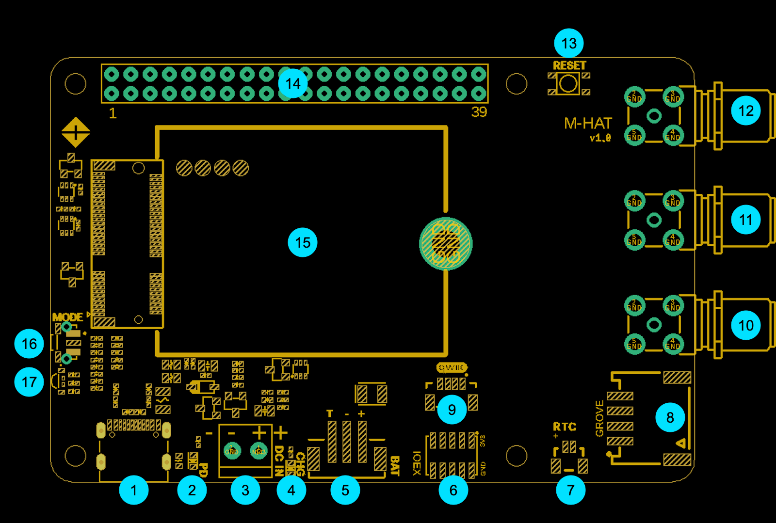
Board Diagram
| Label | Component |
|---|---|
| 1 | USB-C Connector |
| 2 | USB-C PD LED |
| 3 | DC IN (screw terminals) |
| 4 | Charge LED |
| 5 | LiPo Battery Connector |
| 6 | I/O Expansion (IOEX) Header |
| 7 | RTC Battery Connector |
| 8 | Grove Connector |
| 9 | Qwiic Connector |
| 10 | SMA: GNSS |
| 11 | SMA: BLE |
| 12 | SMA: Cellular |
| 13 | RESET Button |
| 14 | 40-pin HAT Connector |
| 15 | Particle M.2 SoM Slot |
| 16 | MODE Button |
| 17 | Particle RGB LED |
USB-C
The USB-C connector provides power to the M-Hat via USB-C PD (Power Delivery), and also exposes the Particle SoM for programming from a computer.
The M-Hat negotiates 9V via USB-C PD. Standard USB-A ports are fixed at 5V and cannot supply enough power for the cellular modem and Raspberry Pi together. Use a USB-C PD adapter.
Do not connect the M-Hat USB-C and the Raspberry Pi's USB-C at the same time.
USB-C PD LED
A small LED near the USB-C connector that illuminates when the USB-C PD negotiation has succeeded at 9V. If this LED is off while a USB-C cable is connected, the adapter does not support PD; replace it with a PD-capable adapter.
DC IN
Two screw terminals accept 5V to 12V DC from an external regulated supply. An onboard boost-buck converter regulates this to the voltages required by the SoM and Raspberry Pi. Suitable for fixed industrial installations with a regulated DC rail.
Charge LED
Indicates the battery charging state. See the Power Guide for the full LED state table.
LiPo Battery Connector
3-pin JST-PH (2mm pitch) connector for a 3.7V LiPo battery with integrated 10K NTC thermistor. The third pin carries the thermistor signal used for temperature-safe charging. See the Power Guide for compatibility notes and the NTC jumper details.
I/O Expansion (IOEX) Header
A 5×2 pin header exposing spare GPIO from the Particle M.2 SoM connector, plus ground and 3.3V. Use this for attaching custom digital I/O, such as logic analyzers, custom circuits, or sensors not covered by Qwiic/Grove.
| Pin | Signal | Direction | Notes |
|---|---|---|---|
| 1 | GND | N/A | Ground |
| 2 | 3V3 | Output | 3.3V rail |
| 3–18 | GPIO (×8) | Configurable | Spare GPIO from M.2 connector |
RTC Battery Connector
A 2-pin 1mm-pitch connector for a Raspberry Pi 5 compatible RTC coin cell. Maintains the AB1805 real-time clock when all other power is removed. Does not supply general board power.
Grove Connector
A standard Grove (4-pin, 2mm pitch) connector providing access to two analog inputs from the Particle SoM. Powered by 3V3_AUX (must be enabled in firmware; see Power Guide).
| Pin | Signal | SoM GPIO |
|---|---|---|
| 1 | GND | N/A |
| 2 | 3V3_AUX | N/A |
| 3 | A2 | Analog input |
| 4 | A1 | Analog input |
For compatible sensors and accessories, browse the Grove ecosystem.
Qwiic Connector
A single Qwiic (JST-SH 4-pin, 1mm pitch) connector on the I2C bus of the Particle SoM. Powered by 3V3_AUX (must be enabled in firmware; see Power Guide).
The Qwiic and Grove connectors will not supply power until the one-time firmware configuration for 3V3_AUX has been run. See the Power Guide or Setup Guide for the configuration snippet.
For compatible sensors, browse the SparkFun Qwiic ecosystem.
SMA Connectors: Cellular, GNSS, and BLE
Three SMA connectors on the M-Hat connect to the Particle SoM's U.FL antenna ports via the included SMA to U.FL adapters:
- Cellular SMA: connects to the SoM's cellular antenna U.FL port
- GNSS SMA: connects to the SoM's GNSS antenna U.FL port
- BLE SMA: connects to the SoM's Bluetooth antenna U.FL port
External antennas are required for cellular and GNSS operation. If using a custom enclosure, route the SMA connectors through panel-mount holes.
RESET Button
Resets the Particle SoM. Does not affect the Raspberry Pi. Equivalent to pressing RESET on a standalone Particle device.
40-pin HAT Connector
An extended 40-pin pass-through header (3mm taller than standard) that connects to the Raspberry Pi GPIO header and passes through signals to HATs stacked above. The extension height allows the M-Hat to clear components on the Pi while still allowing HAT stacking.
UART tethering pins (between SoM and Pi):
| RPi GPIO | Function | SoM Signal |
|---|---|---|
| GPIO14 (TXD) | Pi UART TX → SoM RX | Serial1 RX |
| GPIO15 (RXD) | Pi UART RX ← SoM TX | Serial1 TX |
| GPIO16 (CTS) | Hardware flow control | Serial1 CTS |
| GPIO17 (RTS) | Hardware flow control | Serial1 RTS |
Pi power control pin:
| RPi GPIO | SoM GPIO | Function |
|---|---|---|
| GPIO4 | D8 (CS) | SoM controls Pi power via PFET; 10K pull-up to 3V3 on Pi side |
UART supports up to 921k baud (target: 1M baud). Hardware flow control is supported.
Particle M.2 SoM Slot
Standard Particle M.2 slot accepting B-Series and M-Series SoMs. Insert the SoM at a 45° angle, press down until flat against the board, and secure with the included thumbscrew. See Step 1 of the Install and Setup Guide for full assembly instructions.
MODE Button
Puts the Particle SoM into listening mode for device setup. See Particle LED States for the full mode reference.
Particle RGB LED
A standard Particle device status LED driven entirely by the Particle SoM. It is not affected by the Raspberry Pi. For the authoritative reference on all LED color and pattern meanings, see the Particle LED States page.
GPIO Summary
| SoM GPIO | M.2 Pin | Direction | Function |
|---|---|---|---|
| D4 | N/A | Input | TMP112A temperature alert (use INPUT_PULLUP) |
| D5 | N/A | Input | AB1805 RTC interrupt (use INPUT_PULLUP) |
| D7 | N/A | Output | 3V3_AUX enable (Qwiic/Grove power) |
| D8 | N/A | Output | Raspberry Pi power control (PFET) |
| A0 | N/A | Output | UART isolation bridge enable (HIGH = enabled) |
| A1 | N/A | Input | Grove analog input 1 |
| A2 | N/A | Input | Grove analog input 2 |
| A3 | 37 | Output | LiPo boost converter enable (HIGH = off) |
| A4 | 41 | Output | DC/USB boost-buck enable (HIGH = off) |
| A7 | N/A | Input | PMIC interrupt |
I2C Address Map
The following peripherals are on the Particle SoM I2C bus. Note that the SoM and Raspberry Pi I2C buses are not shared by default (solder bridges are available to bridge them if needed).
| I2C Address | Peripheral | Function |
|---|---|---|
| 0x28 | STUSB4500 | USB-C PD controller |
| 0x36 | MAX17043 | Fuel gauge (battery state of charge) |
| 0x48 | TMP112A | Temperature sensor |
| 0x69 | AB1805 | RTC / Watchdog |
| 0x6B | bq24195 | PMIC (battery charger) |
Internal Peripherals
STUSB4500 (USB-C PD Controller)
Handles USB-C Power Delivery negotiation to obtain 9V from the connected adapter. For B-Series SoMs, the NFC pins must be reconfigured via UICR to be available as general GPIO. If using those pins, see the NFC_UICR_RK library.
FSA2567 (UART Isolation)
A UART isolation switch between the Particle SoM and the Raspberry Pi. Isolated by default; A0 must be set HIGH explicitly in firmware before Tether calls. The Tether API does not handle this automatically.
pinMode(A0, OUTPUT);
digitalWrite(A0, HIGH); // enable UART bridge
TMP112A (Temperature Sensor)
A precision I2C temperature sensor on the SoM I2C bus. The SoM and Raspberry Pi I2C buses are not shared. Alert pin connected to D4; use INPUT_PULLUP:
pinMode(D4, INPUT_PULLUP);
AB1805 (RTC / Watchdog)
Real-time clock and watchdog timer, maintained by the RTC coin cell battery when main power is removed. Interrupt pin connected to D5; use INPUT_PULLUP:
pinMode(D5, INPUT_PULLUP);
PM-BAT Power Module
Manages the PMIC, battery charger, and fuel gauge. A7 receives PMIC interrupts; D7 controls 3V3_AUX. See Power Guide for configuration.