M-Hat Power Guide
The M-Hat manages power for both itself and the Raspberry Pi. Getting power right is essential - an undersupplied board may boot inconsistently or fail to connect.
Power Sources
The M-Hat can be powered from any of the following:
| Source | Notes |
|---|---|
| USB-C (recommended) | Requires USB-C PD support to negotiate 9V |
| DC IN | 5V to 12V via 2-pin screw terminals |
| LiPo Battery | 3.7V via 3-pin JST-PH connector |
| HAT connector (5V IN) | From a PoE HAT or other power-supplying HAT stacked below |
USB-C Power Requirements
USB-A to USB-C cables will NOT power the M-Hat.
The M-Hat uses USB-C Power Delivery (PD) to negotiate 9V from the power adapter. Standard USB-A ports are fixed at 5V and cannot provide sufficient voltage or current for the cellular modem and Raspberry Pi together. This includes Raspberry Pi-branded power adapters that are 5V-only USB-C adapters.
Requirements:
- Adapter type: USB-C PD (Power Delivery) capable
- Negotiated voltage: 9V
- Minimum current: Sufficient for both the Particle SoM cellular modem and Raspberry Pi
- Verification: The USB-C PD LED on the M-Hat illuminates when PD negotiation succeeds at 9V
Do not connect both the M-Hat USB-C and the Raspberry Pi's USB-C at the same time.
See Muon USB Power troubleshooting for more details.
DC IN (5–12V)
The screw terminal DC input accepts 5V to 12V. This is ideal for fixed installations with a regulated industrial DC supply. An onboard boost-buck converter regulates this input to the voltages required by the SoM and Raspberry Pi.
| GPIO | Direction | Function |
|---|---|---|
| A4 | Output | DC/USB boost-buck converter enable (HIGH = off, default on) |
LiPo Battery
The M-Hat includes a LiPo battery connector and onboard charger.
- Connector: 3-pin JST-PH (2mm pitch)
- Battery voltage: 3.7V nominal
- Thermistor required: The connector includes a third pin for a 10K NTC thermistor. The PMIC uses the thermistor reading to enable temperature-safe charging.
The included battery is compatible. Standard 2-pin JST-PH LiPo batteries are NOT compatible; without the thermistor, charging will never activate.
Charge LED States
| LED State | Meaning |
|---|---|
| On (solid) | Battery is charging |
| Off | Battery is fully charged, or no charging power is available |
| Blinking | Battery or charging fault |
If no battery is connected, the charge LED may flicker at boot or in DFU mode, and will blink periodically while the device checks for a battery. This is normal.
Third-Party Batteries
If using a third-party LiPo battery:
- Verify polarity before connecting. JST-PH polarity is not standardized across manufacturers; connecting a reverse-polarity battery can damage the board.
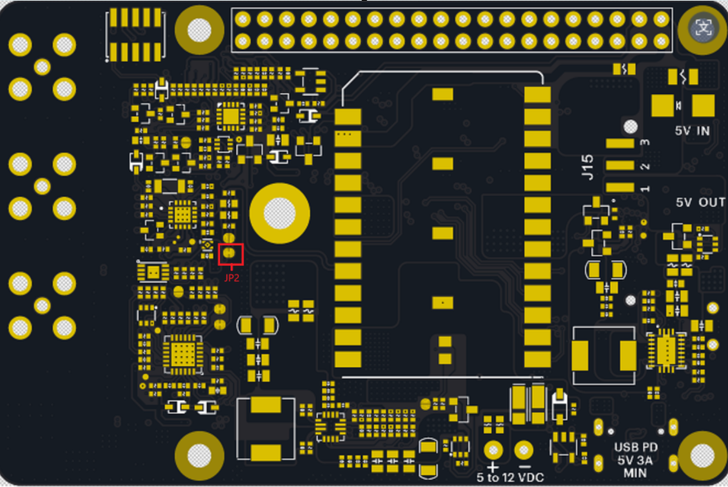
- If using a battery without a 10K NTC thermistor, you must cut the normally closed trace jumper on the bottom of the M-Hat, otherwise charging will never enable. It is located to the left of the power module, with the HAT connector on the side away from you.
| GPIO | Direction | Function |
|---|---|---|
| A3 | Output | LiPo-to-5V boost converter enable (HIGH = off, default on) |
HAT Power Direction (5V Jumper)
A jumper on the bottom of the M-Hat selects the direction of 5V power on the HAT connector. This is an either-or setting; only one power direction should be active at a time.
| Jumper Setting | Who powers whom |
|---|---|
5V_OUT + center (default) | The M-Hat is the power source. It supplies 5V to the Raspberry Pi and any HATs stacked above. Power the M-Hat via USB-C PD, DC IN, or LiPo battery. |
5V_IN + center | The Raspberry Pi or a HAT stacked below (e.g., a PoE HAT) is the power source. It supplies 5V to the M-Hat via the HAT connector. Do not connect USB-C PD, DC IN, or a LiPo as a primary supply in this mode. |
These two modes are mutually exclusive. In 5V_OUT mode, only the M-Hat should be supplying power; do not simultaneously power the system from a HAT below or the Raspberry Pi's own power input. In 5V_IN mode, only the external HAT or Pi should be supplying power; do not simultaneously connect the M-Hat USB-C, DC IN, or rely on LiPo as the primary source. Mixing power directions on the 5V rail can damage the M-Hat, the Raspberry Pi, or both.
Raspberry Pi Current Requirements
The M-Hat's 5V boost converter powers the Raspberry Pi via the 40-pin header. The 3A output must cover the Pi and any additional HATs or USB peripherals. Approximate power requirements by model:
| Raspberry Pi Model | Typical Current | Peak Current |
|---|---|---|
| RPi 3 | ~1.5A | ~2.5A |
| RPi 4 | ~1.8A | ~3.0A |
| RPi 5 | ~2.0A | ~3.5A+ |
Account for any HATs or USB devices attached to the Pi when selecting your power adapter.
RTC Battery
A separate 2-pin 1mm-pitch connector on the M-Hat accepts a standard Raspberry Pi 5 RTC battery module (coin cell type). This maintains the real-time clock (AB1805) when all other power sources are removed. It does not provide general system power to the board.
Power Control: SoM Controlling the Pi
The Particle SoM can control power to the Raspberry Pi using a dedicated PFET, enabling ultra-low power sleep modes and wake-on-demand use cases. GPIO4 on the Pi is connected to the CS pin (D8) on the SoM via the 40-pin header:
// Power down the Raspberry Pi from the Particle SoM
pinMode(D8, OUTPUT);
digitalWrite(D8, LOW); // sets GPIO4 LOW on the Pi
GPIO4 has a 10K hardware pull-up to 3V3 on the Pi side.
The Raspberry Pi does not have a true sleep mode, but consumes significantly less power in HALT mode. Controlling power through D8 is the most effective approach for battery-operated or solar-powered deployments.
Auxiliary Power (3V3_AUX): Qwiic and Grove
The Qwiic and Grove connectors are powered by 3V3_AUX, controlled by D7. This is configured automatically by the web setup. If configuring manually:
One-time setup (enables 3V3_AUX automatically at boot):
// Reset device after running once.
SystemPowerConfiguration powerConfig = System.getPowerConfiguration();
powerConfig.auxiliaryPowerControlPin(D7).interruptPin(A7);
System.setPowerConfiguration(powerConfig);
Manual control (if you prefer to manage it yourself):
SystemPowerConfiguration powerConfig = System.getPowerConfiguration();
powerConfig.auxiliaryPowerControlPin(PIN_INVALID).interruptPin(A7);
System.setPowerConfiguration(powerConfig);

// In setup():
pinMode(D7, OUTPUT);
digitalWrite(D7, 1); // turn on 3V3_AUX
digitalWrite(D7, 0); // turn off 3V3_AUX
Until the PMIC is configured, USB input current is limited to 100mA - insufficient for the SoM to boot with high-current peripherals connected. The power manager holds 3V3_AUX off until after the PMIC negotiates a higher current limit from the USB-C host.
Common Power Issues
| Symptom | Likely Cause | Fix |
|---|---|---|
| M-Hat won't power on from USB | USB-A to USB-C cable, or non-PD adapter | Use a USB-C PD adapter that supports 9V |
| USB-C PD LED not lit | Adapter doesn't support PD | Swap to a PD-capable adapter |
| Charge LED blinking | Battery or charger fault | Check battery polarity; verify thermistor connector |
| Qwiic/Grove not working | 3V3_AUX not enabled | Run web setup or manual firmware config above |
| Pi randomly reboots | Insufficient 5V current | Use a higher-current PD adapter; check HAT jumper direction |
| SoM not visible over USB | Charge-only USB-C cable | Use a data-capable USB-C cable |
| Charging never starts | No thermistor on battery | Cut the normally closed trace jumper on the bottom of the M-Hat; see LiPo Battery above |