🛠️ Assembling with Muon
In this section, you'll learn how to install a Particle Muon into the M1 enclosure—perfect for remote, headless deployments in rugged environments.
But before diving in, make sure you’ve got all the gear ready!
✅ What You’ll Need

- M1 Enclosure Kit
- Particle Muon
- Particle M-SoM (all versions are supported)
- Phillips head screwdriver
- Flat head screwdriver (optional)
Setup
Accessing the M1 carrier board
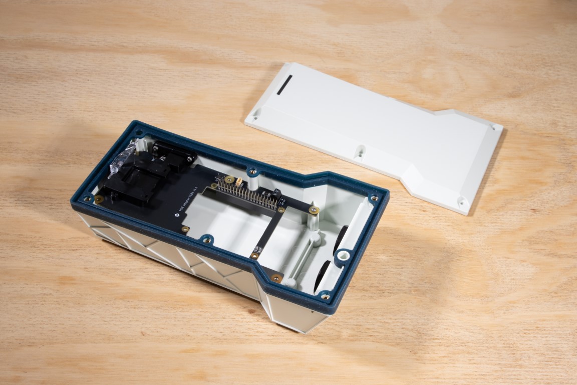
We’ll start by removing the top lid of the enclosure to reach the carrier board.
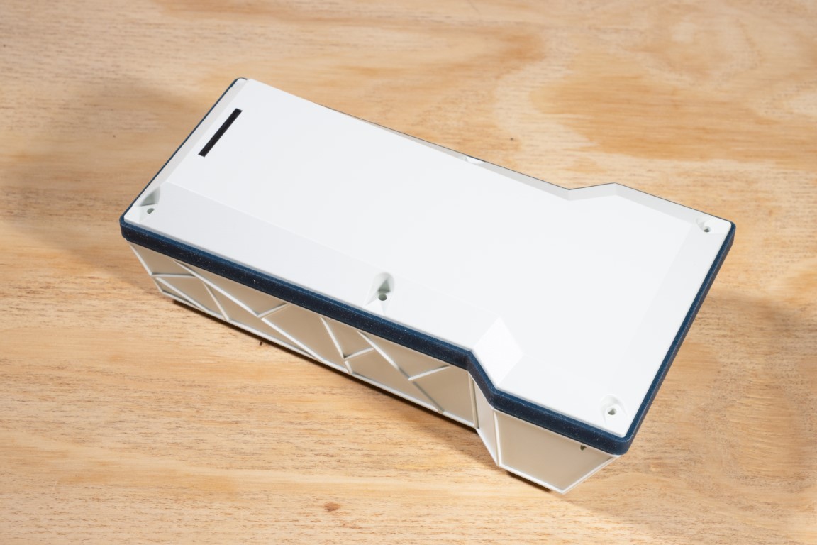
The lid isn’t fastened with screws—just lift it off.
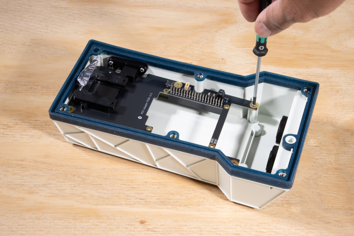
Use a Phillips head screwdriver to remove the three screws holding the carrier board in place. Don’t worry about the other three—you’ll find them in your kit. We pre-installed just three to make your first removal easier.
Gently lift up the carrier board and remove it from the enclosure.
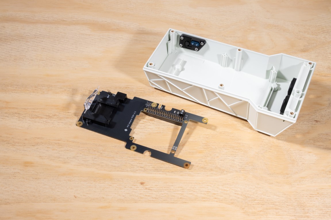
Want to explore the carrier board in detail? We’ve documented that here.
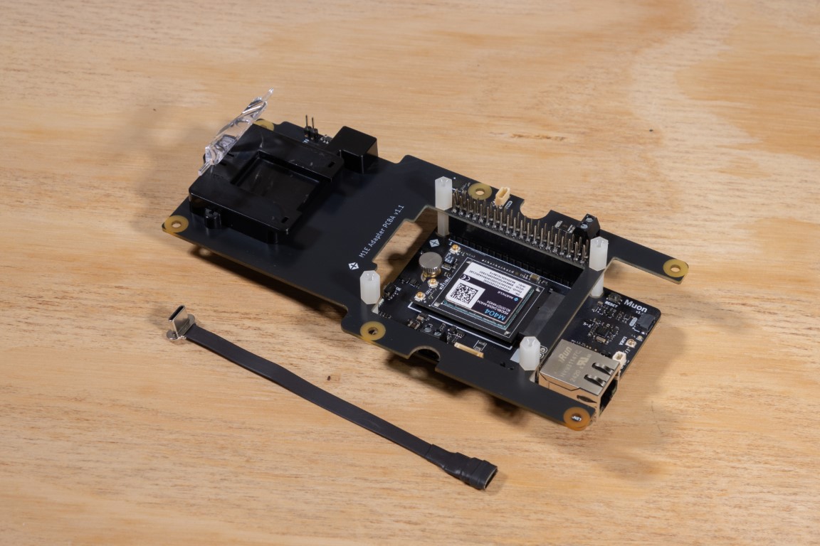
Preparing the Muon
Now let’s prep the Muon for mounting. You’ll need the Muon and the nylon screws and threaded spacers from the kit.
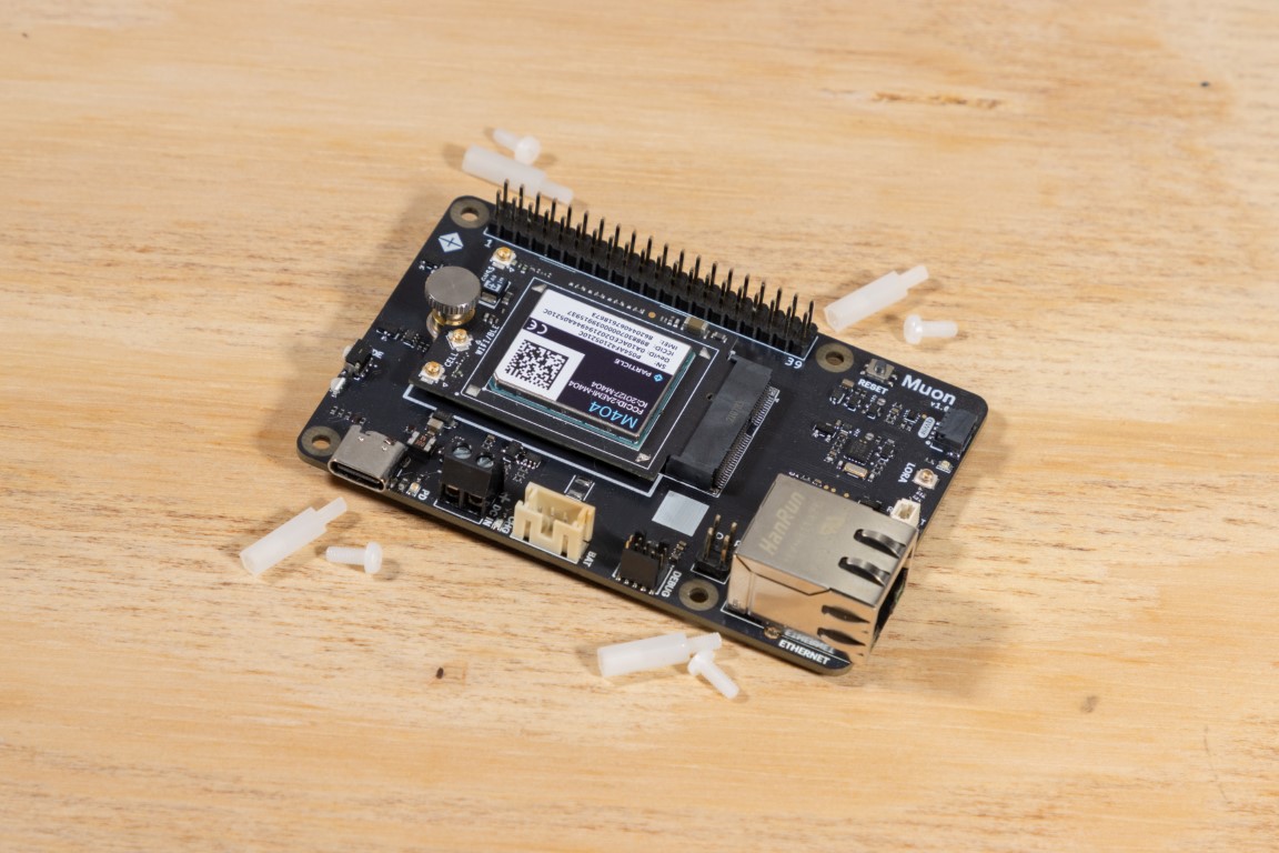
Install the four nylon spacers into the mounting holes on the Muon.
Once installed, it should look something like this.
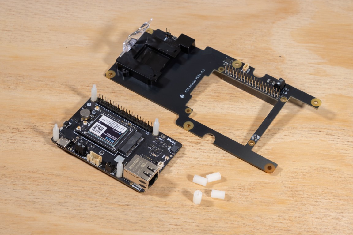
Installing the Muon onto the Carrier Board
Line up the Muon with the carrier board.
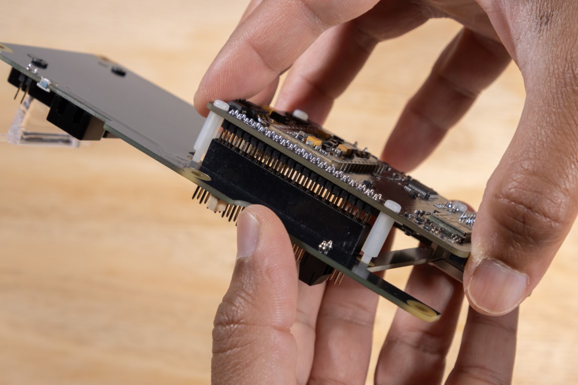
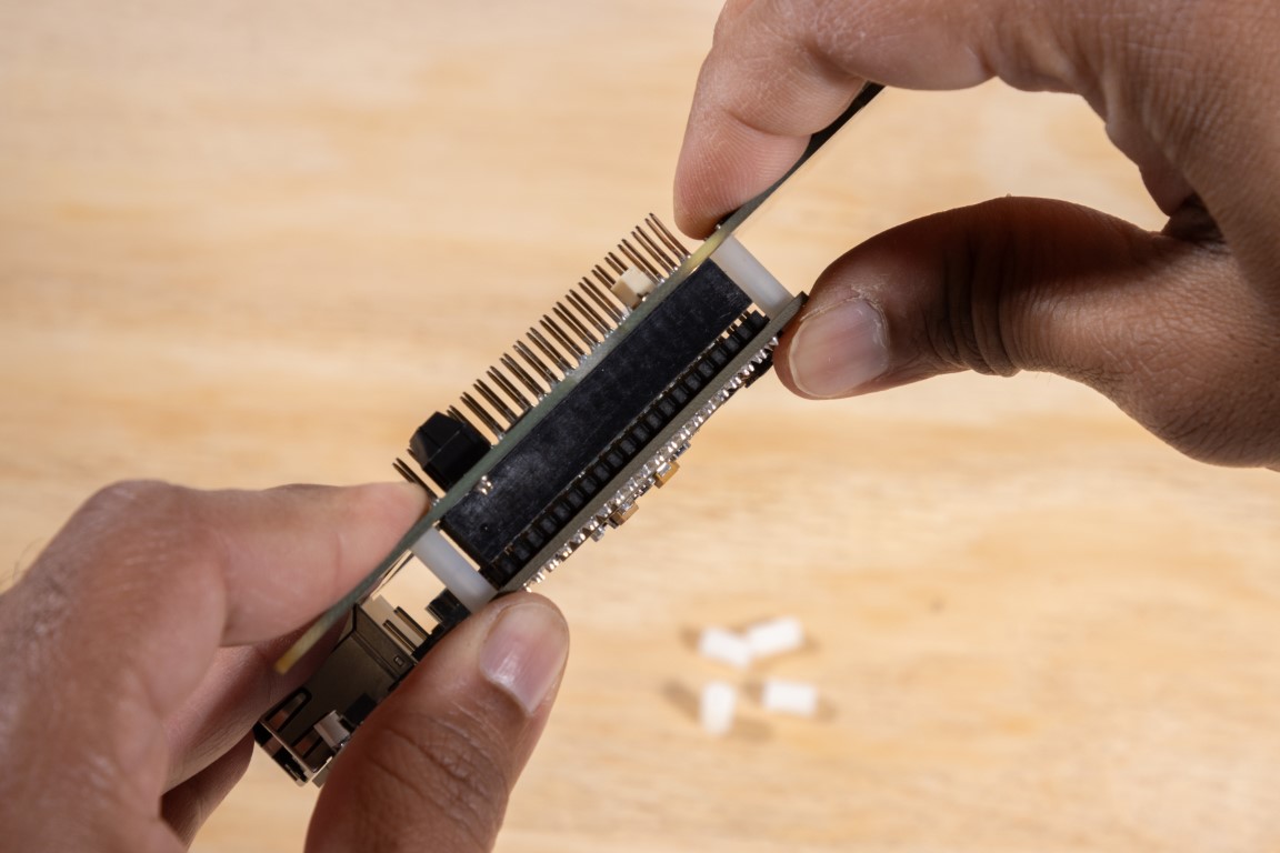
Carefully align the 40-pin header with the socket on the carrier board. Also make sure the spacers fit into the holes.
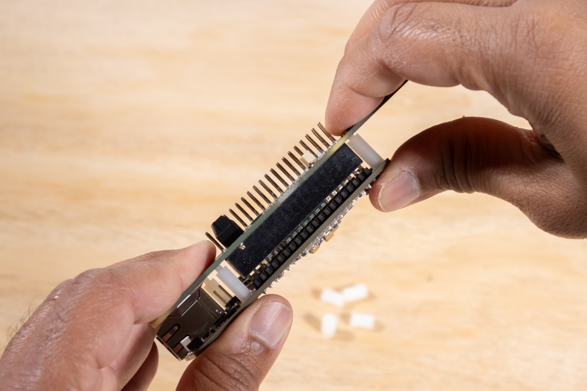
Gently press down on both sides. You should see a small 1mm gap between the connectors—this is intentional. Don’t try to push it all the way in.
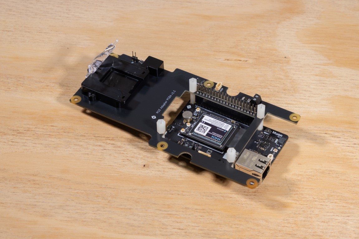
Use the provided spacers to secure the Muon to the board.
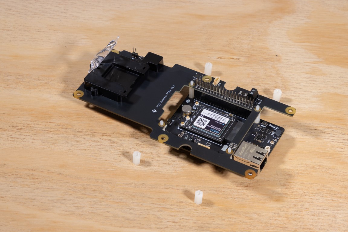
This setup leaves room for HATs or other accessories to be installed later.
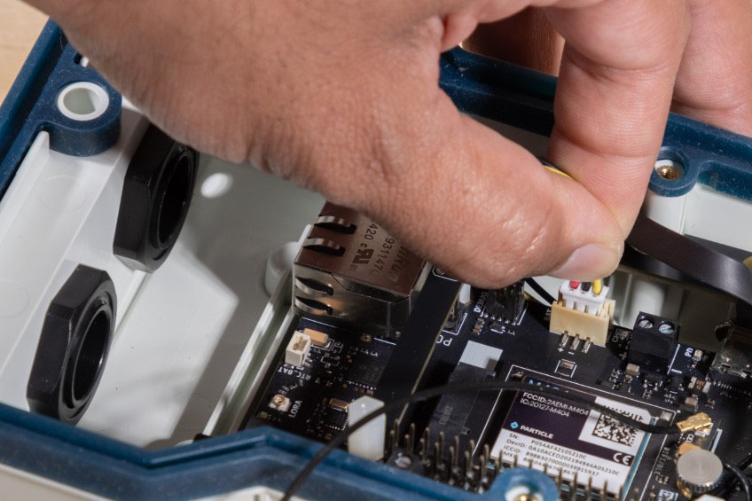
Installing the USB-C Adapter Cable
Your kit comes with a custom angled USB-C cable that routes neatly through the enclosure.
Even if you don’t plan to use USB-C right away, we recommend plugging it in now. You won’t be able to access the port once the board is mounted.
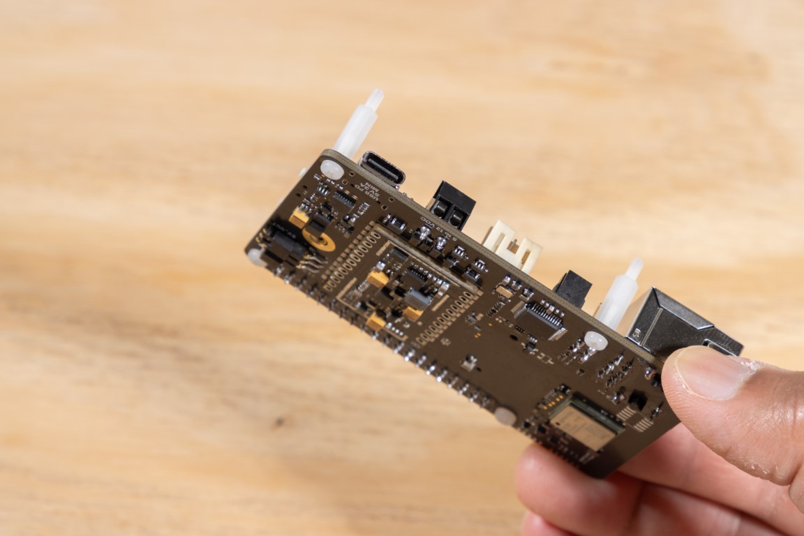
🔌 Power Input Selection Jumper
Before continuing with the assembly, take a moment to decide how you want to power your Muon.
If you're planning to power it using just the USB-C cable or the built-in battery, you can go ahead and skip this section.
However, if you’re planning to use:
- the 5V terminal block on the carrier board
- a Power-over-Ethernet (PoE) HAT
- or any other power HAT
...then you’ll need to set the correct jumper configuration.
You can find this jumper underneath the Muon, near the 40-pin header area.
⚙️ Default: 5V_OUT
By default, the jumper is set to 5V_OUT.
This means the Muon will supply 5V to an attached HAT via the 40-pin header.
Use this setting if you're powering the Muon via USB-C or battery and want to also power a HAT connected on top.
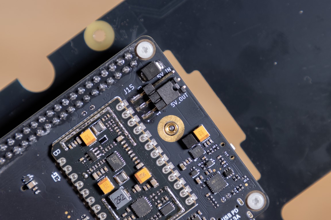
With the jumper set to 5V_OUT, the Muon will send power to the HAT.
🔁 Switching to 5V_IN
If you want the Muon to be powered by an external HAT (e.g., a PoE or power regulation HAT), move the jumper to the 5V_IN position.
This configuration tells the Muon to receive 5V through the 40-pin header instead of supplying it.
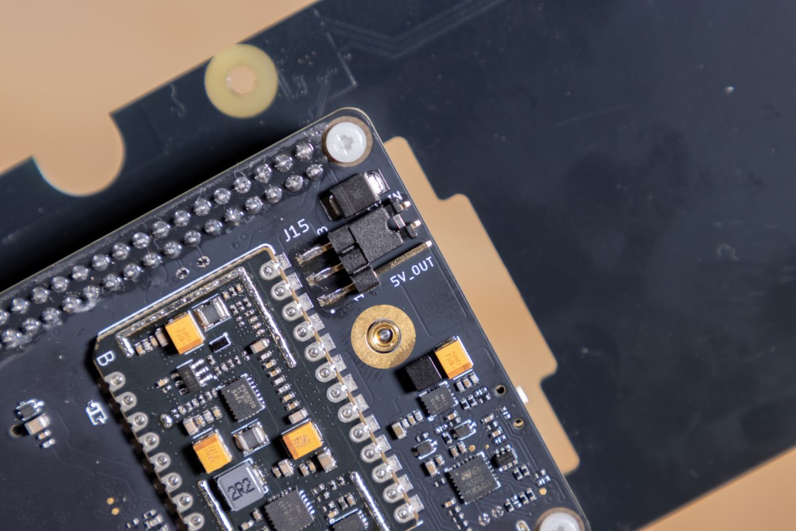
Set the jumper to 5V_IN if you're powering the Muon from a HAT or through the 5V pin.
💡 Don’t worry—you can still keep the USB-C and/or battery connected. The Muon’s power system handles all sources safely.
Summary:
| Scenario | Jumper Setting |
|---|---|
| Powering Muon with USB-C or battery | 5V_OUT (default) |
| Powering a HAT from the Muon | 5V_OUT |
| Powering the Muon from a HAT or 5V terminal block | 5V_IN |
Double-check this setting before powering up your system!
Installing the Battery
One of the most interesting and useful feature of Muon is its native support for Li-Ion/Li-Po battery. If you purchased a 3-cell battery pack or if your Muon came with a single-cell battery, now is the time to install it.
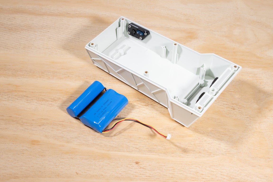
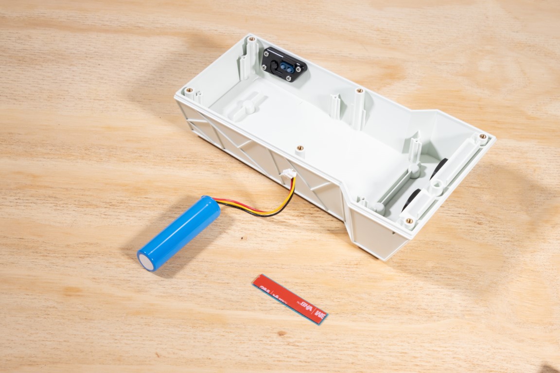
If you are installing the 1-cell battery, then you can use the double sided tape that came with your M1 kit.
We will be using the 3-cell pack in this guide. This pack comes with an adhesive tape. Simply peel it off and install the battery inside the enclosure as shown.
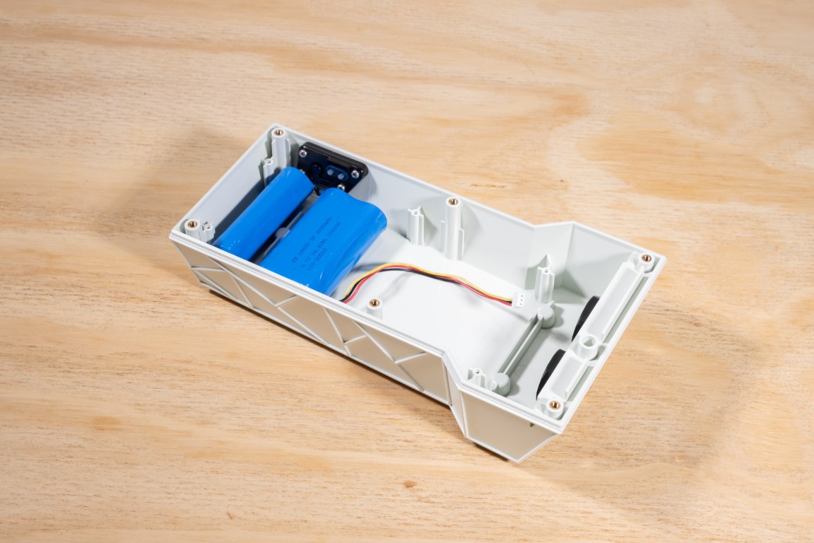
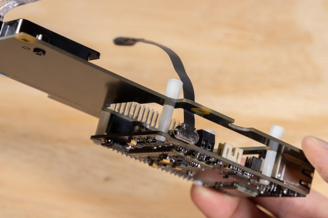
Route the battery cable along the side of the carrier board to the top. Make sure it does not interfere with any of the connectors or get accidentally pinched.
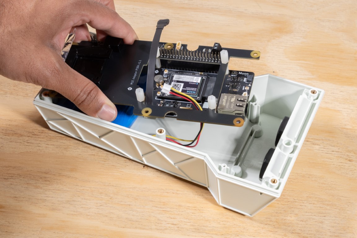
Place the carrier board assembly inside the enclosure and line up the six holes against the posts inside. The board should lay completely flat. Do not plug in the battery just yet!
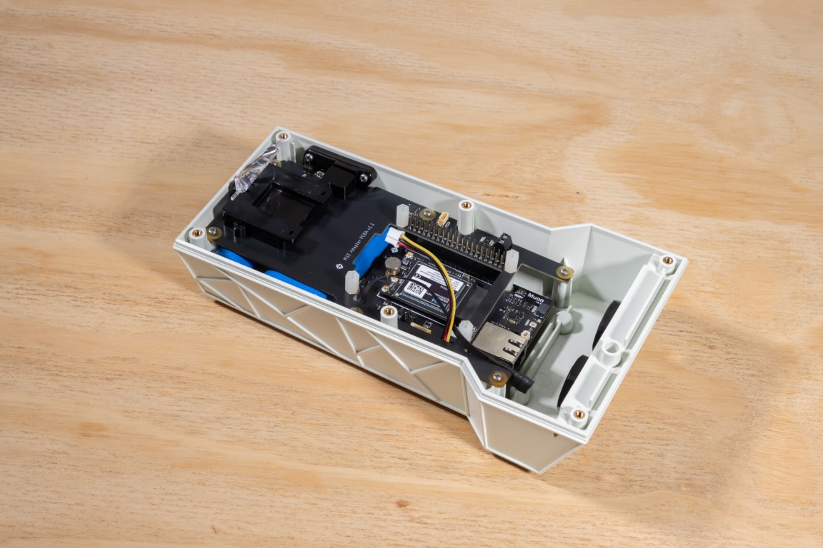
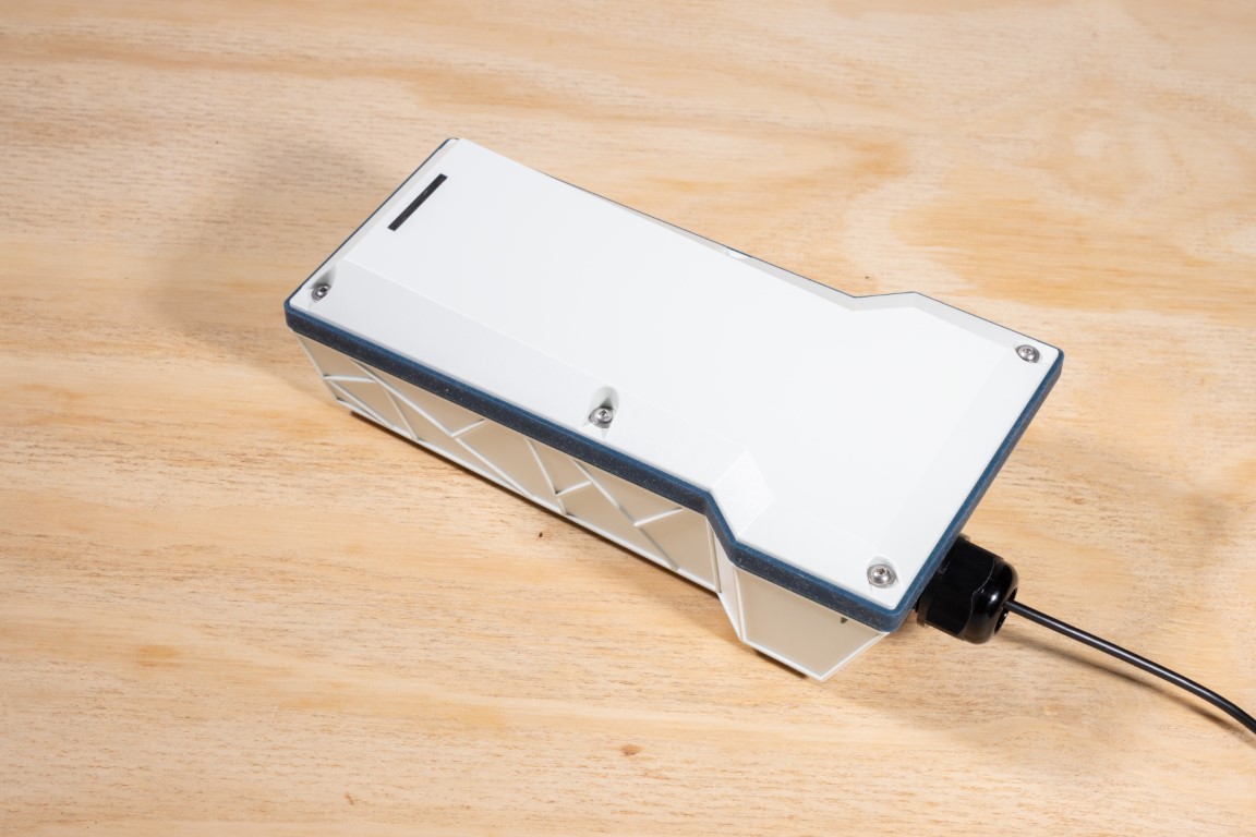
Installing the Cable Glands
To bring in power or data cables, use the M20 cable glands. The enclosure has two sealed M20 holes and two for optional SMA connectors (antenna ports).
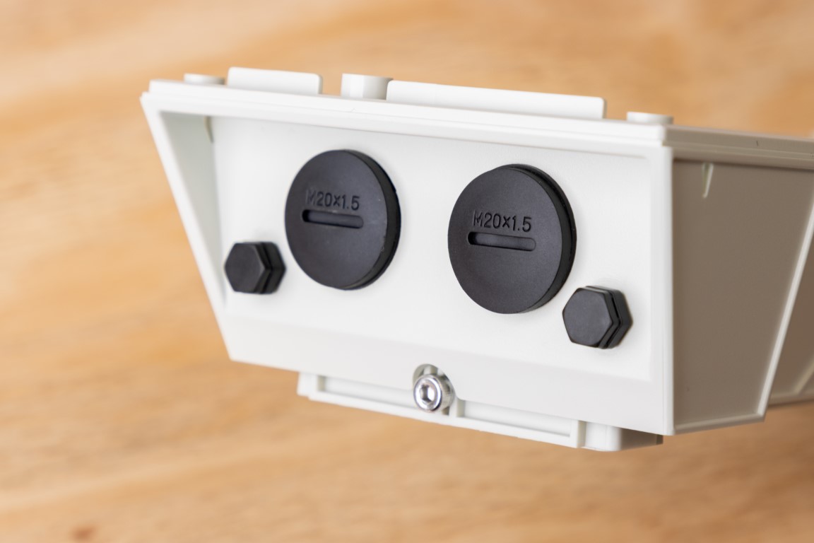
Planning to bring out only the USB cable? Just remove one M20 cap and install the gland from the kit.
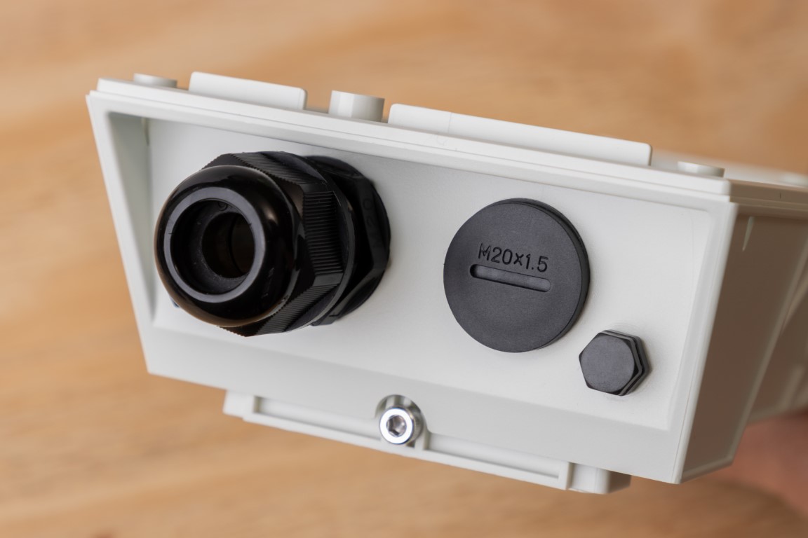
To ensure an IP67 seal, tighten to about 7 kgf-cm.
📡 Installing the Antennas
The Muon is a multi-radio device, and depending on your configuration (e.g., with an MSoM), it can support:
- Cellular
- Wi-Fi/BLE
- GNSS (GPS)
In this section, we’ll show how to mount these antennas inside the enclosure for optimal placement and minimum cross-interference.
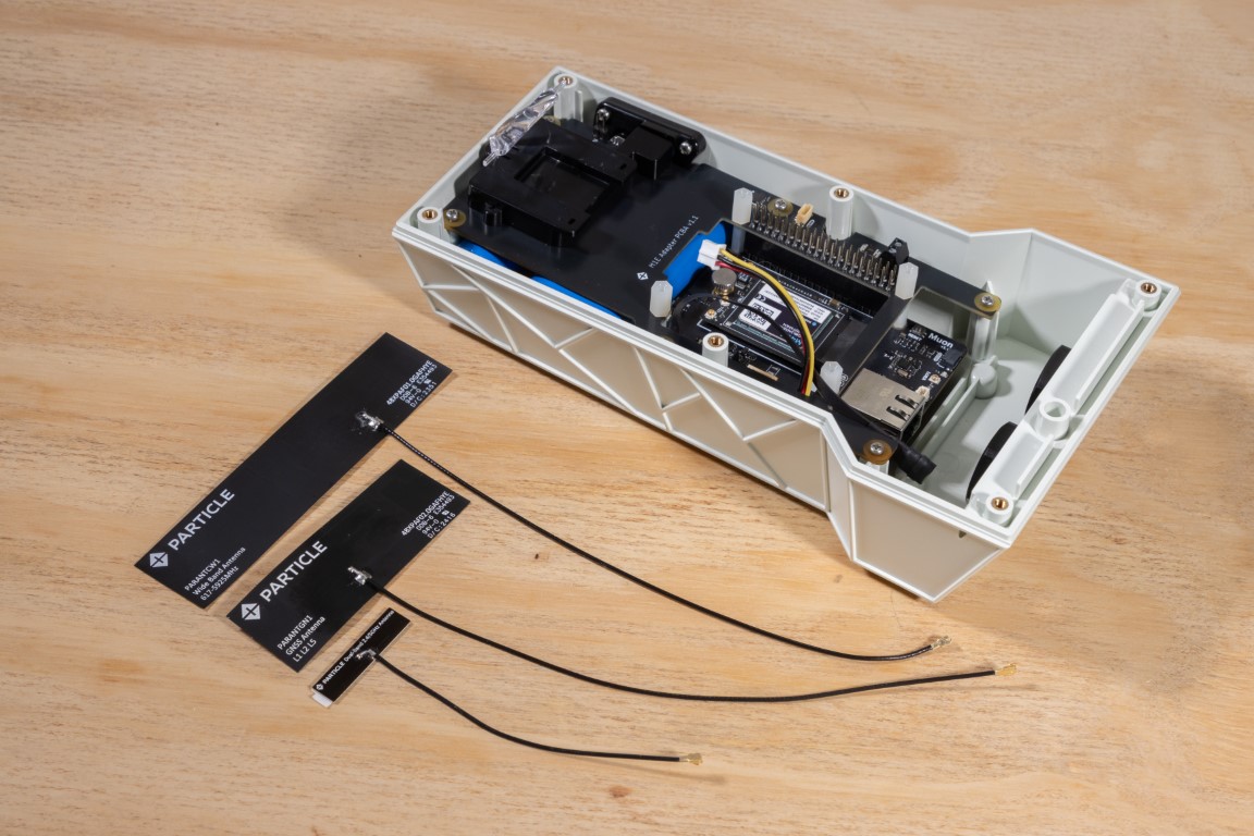
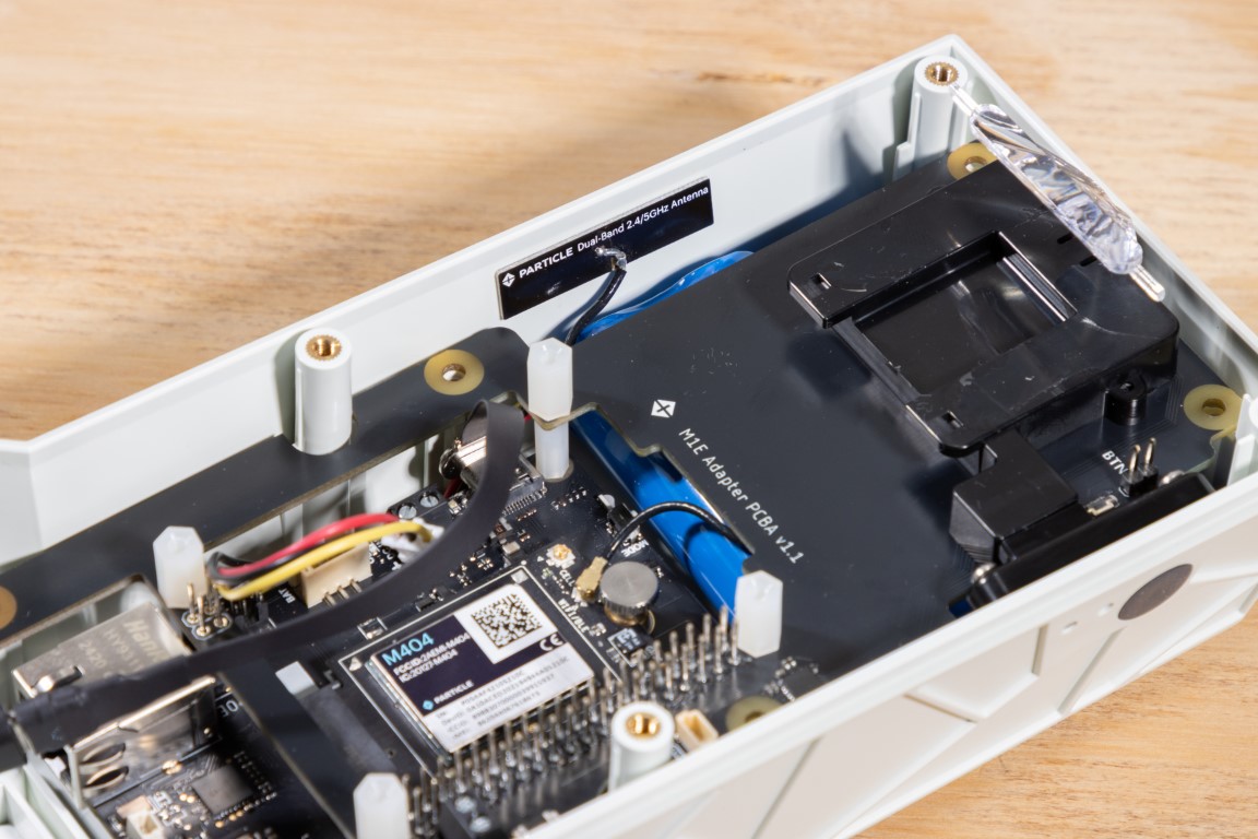
Start by placing the dual-band Wi-Fi/BLE antenna inside the enclosure, as shown below.
Route the antenna’s feedline underneath the carrier board and connect it to the MSoM.
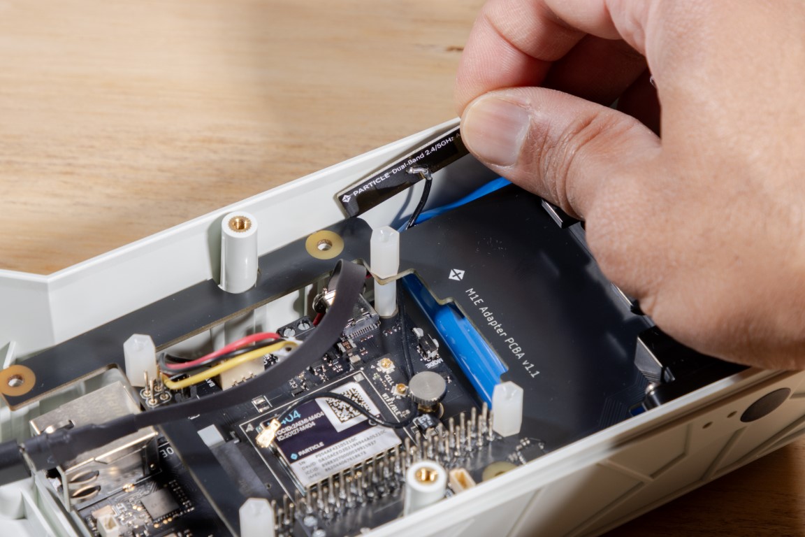
Dry fit the antenna first to confirm placement. Once you’re happy with the location, peel off the adhesive backing and stick the antenna in place.
Next, mount the passive GNSS antenna and the cellular antenna on the inside of the enclosure’s lid.
Again, dry fit first, then remove the adhesive backing and carefully press them in.
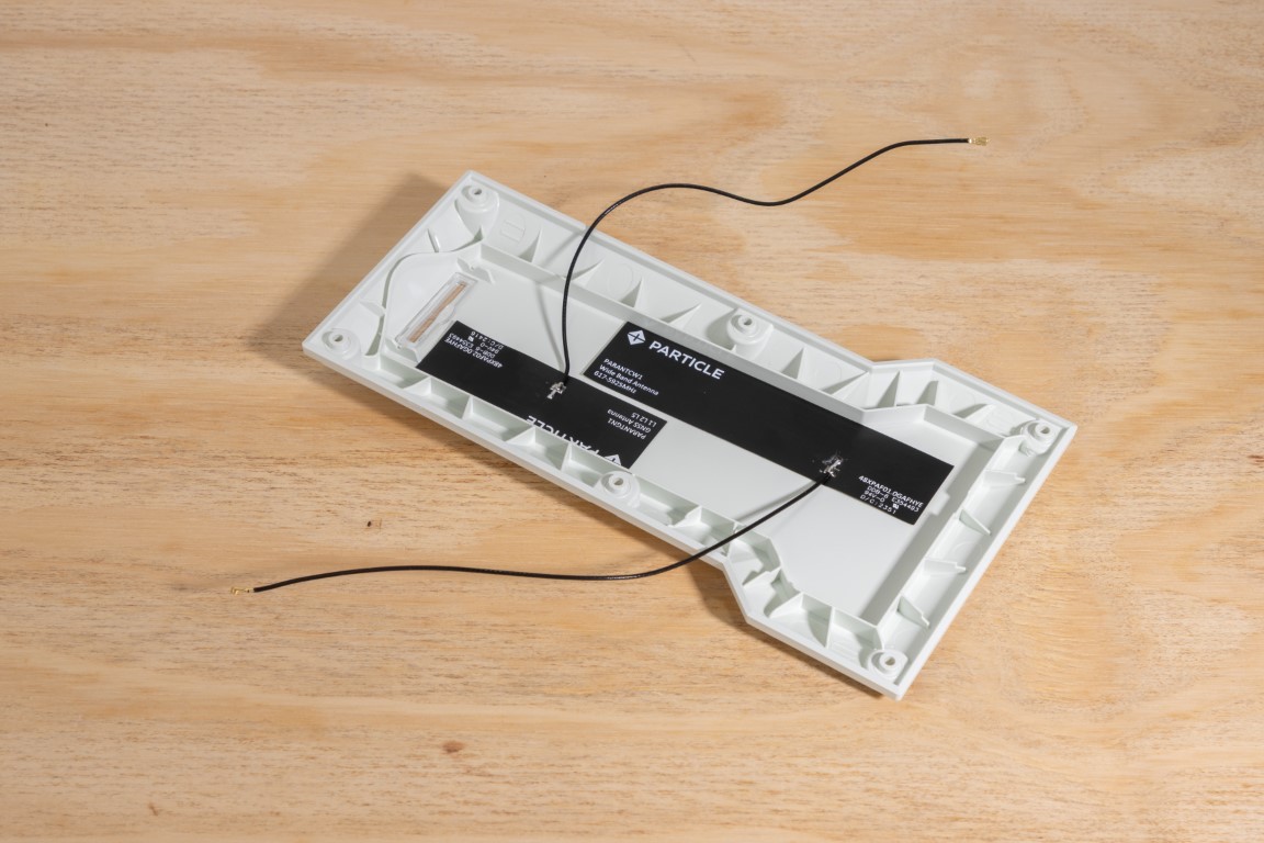
Make sure the antennas are spaced apart and mounted flat for best signal performance.
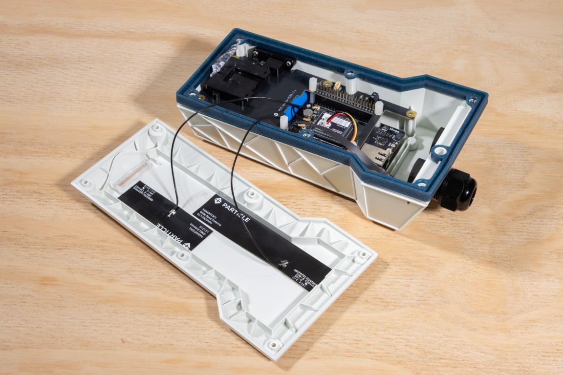
Before plugging in the u.FL connectors to the MSoM, install the silicone gasket on the enclosure.
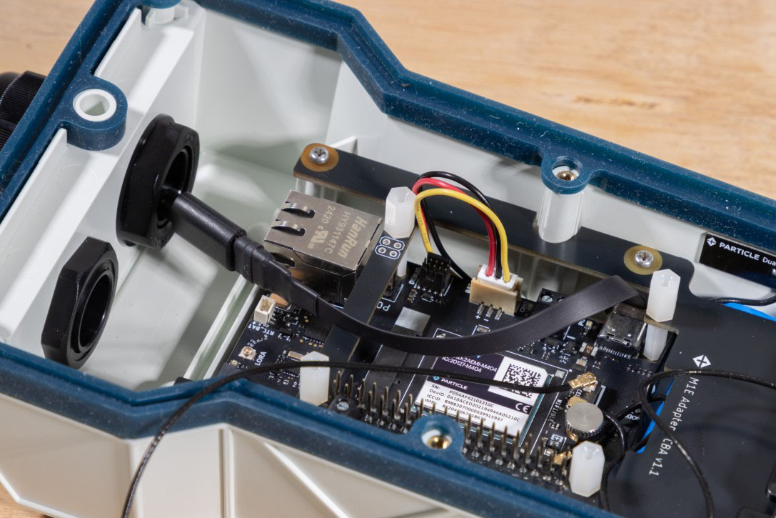
Then plug in the 3-pin battery connector into the socket on the Muon.
Note: The connector only fits one way—don’t force it.
Now thread the USB cable through the cable gland and secure the carrier board using all six self-tapping screws—the original three plus three from the kit.
We asked you to wait on plugging in the battery until now for a reason:
It’s easy to accidentally drop a screw while securing the board. If your battery had been connected already, a loose screw could have shorted a component and released the magic smoke! 💨
Always install screws before applying power.
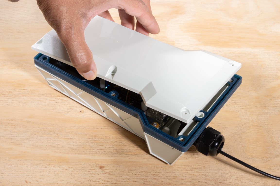
Now carefully place the lid on the enclosure. Take care not to pinch any antenna wires during this step.
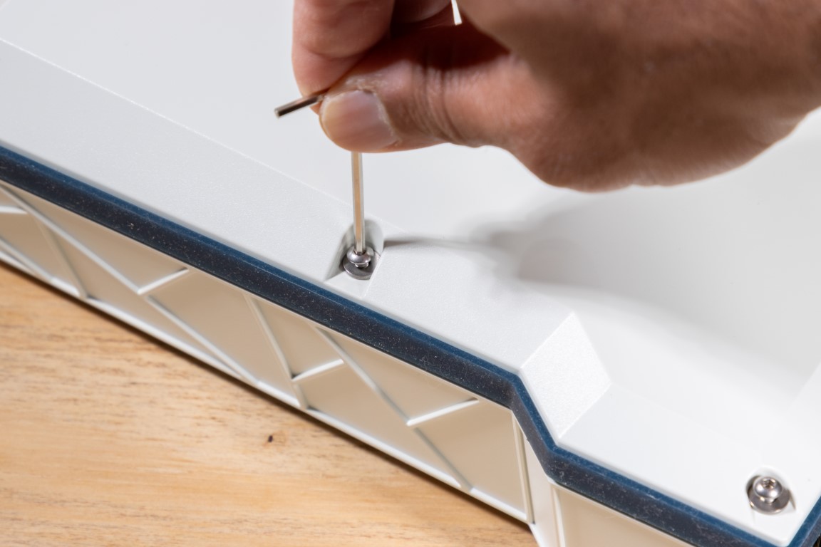
Secure the lid using the six M3 screws and washers. Use the smaller Allen key from the kit. To maintain the IP67 weather rating, tighten the screws to approximately 7.5 kgf-cm.
🎉 That’s it! Your Muon is now rugged, sealed, and ready for the real world.
⚡ Powering Your Device
There are several ways to supply power to your Muon inside the M1 enclosure. The most straightforward is via USB-C, as we covered earlier—but that’s not your only option.
1. 5V Terminal Block on the Carrier Board
The M1 carrier board breaks out the Muon’s 5V and GND lines to a convenient 2-pin terminal block.
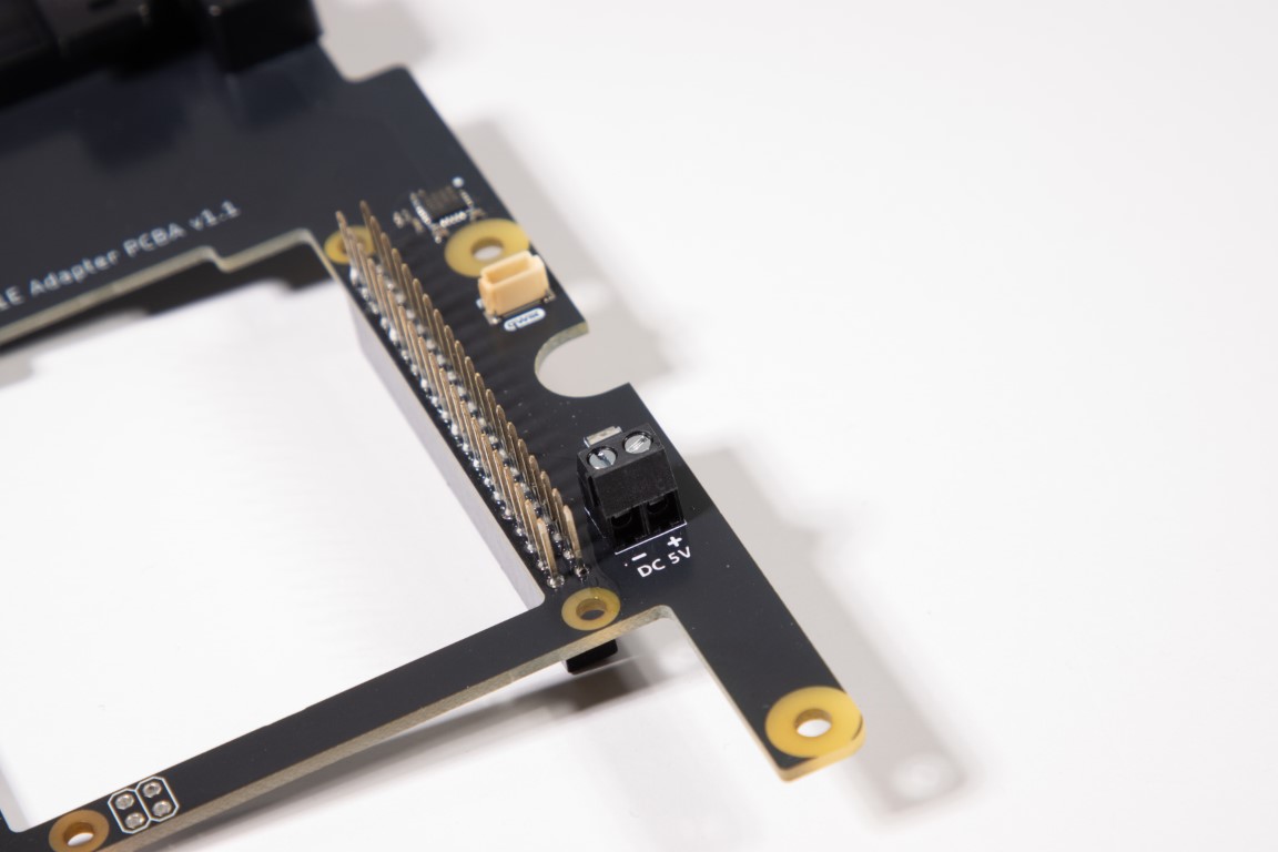
Use it to bring power using plain wires. Make sure your power source provides 5V at 3 Amps, which is the minimum recommended spec for the Muon. Also make sure that the power selection jumper on the bottom of the Muon is set to 5V_IN.
You can route the cable through a cable gland.
💡 Pro tip: If your wire is too thin for the gland, wrap it with butyl tape to make a tighter seal.
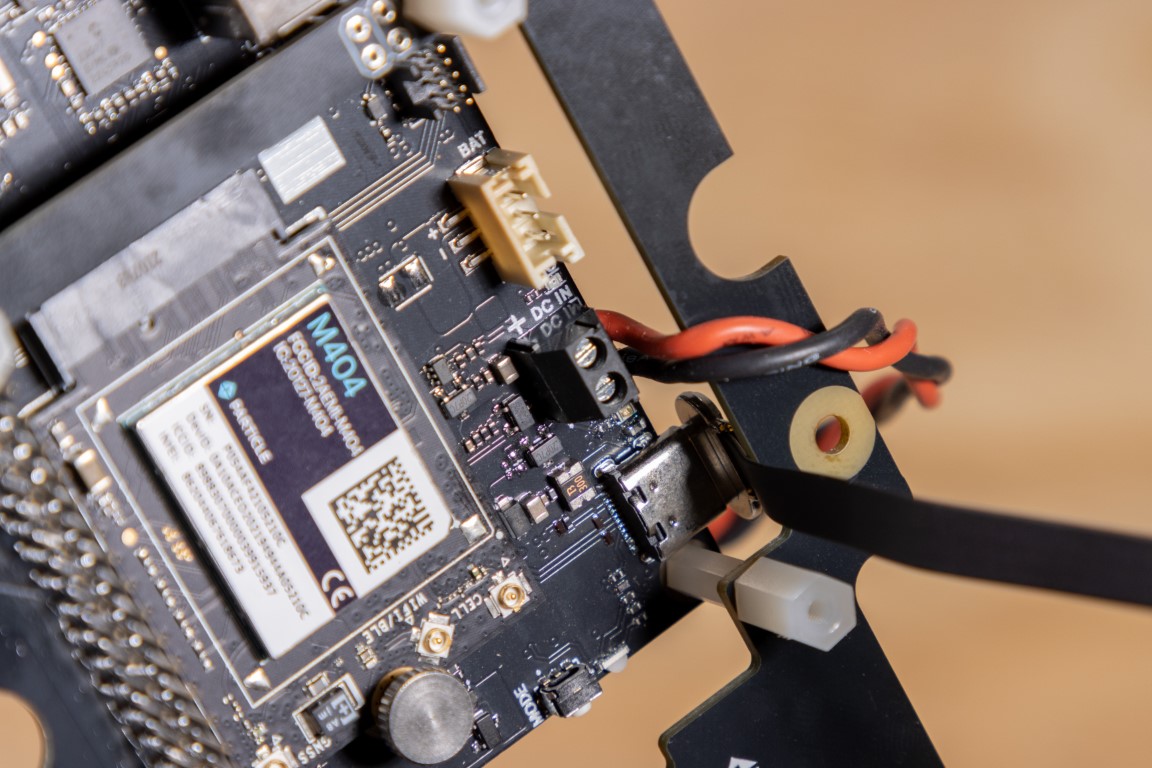
2. Terminal Block on the Muon
Muon also has an onboard 2-pin terminal block to bring power to the device. Unlike the 5V terminal block on the carrier board which brings power via the 5V pin on the 40-pin header, this is a dedicated power input for the Muon with a wider input voltage range of 5V to 12VDC.
3. Power Over Ethernet (PoE)
Muon supports being powered over it's ethernet connection. You'll need a dedicated PoE HAT to enable this feature. The M1 carrier board includes optional pads for a 4-pin PoE header—just solder it on.
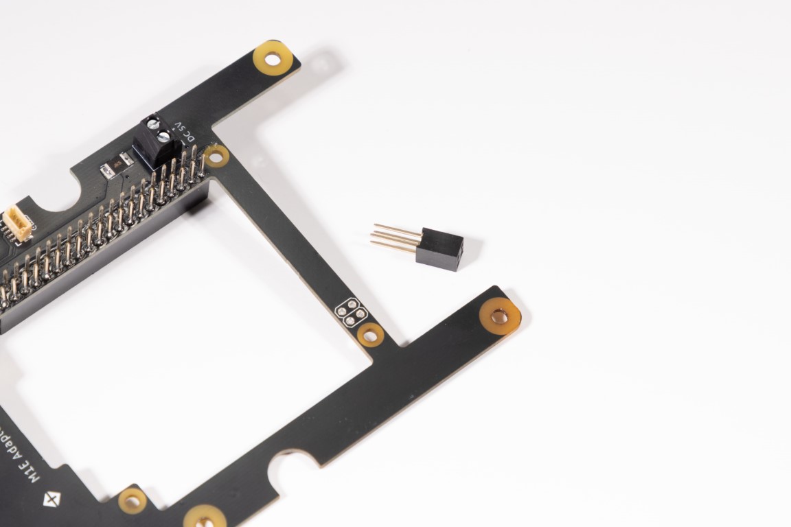
This lets you use a PoE HAT to deliver both power and ethernet through a single cable.
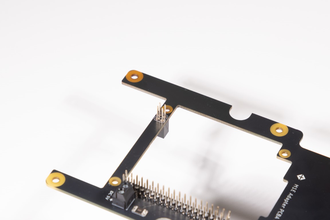
Make sure the header is soldered straight—this makes Muon installation easier.
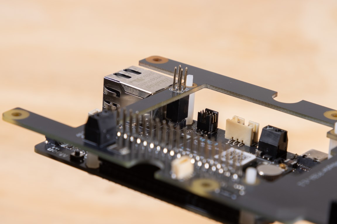
Install your PoE HAT and plug in the Muon like usual.
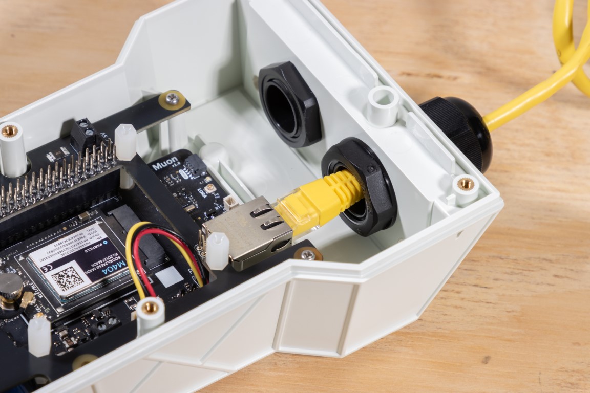
Feed the ethernet cable in through one of the M20 glands.
Note: Bulky RJ45 connectors might be a tight fit.
4. Dedicated Power HATs
There are many off-the-shelf power HATs that can step down 12V or 24V to 5V for the Muon. These are useful for automotive, solar, or industrial deployments.
✨ Enabling Additional Hardware Features
The M1 enclosure has a few extra tricks built-in to help you build a complete, professional-grade product.
1. Using the Onboard RGB LEDs
There are three user-programmable RGB LEDs:
- One on the top (main status LED)
- Two on the side (near the external button)
These are controlled by an onboard ADP8866 I²C LED driver, connected to pins 3 and 5 on the Muon's header (standard I²C).
Its default I²C address is 0x27.

Heads-up: This shares the same I²C bus as the Qwiic connector, so avoid address conflicts.
🔧 A control library for the ADP8866 will be available soon on our GitHub!
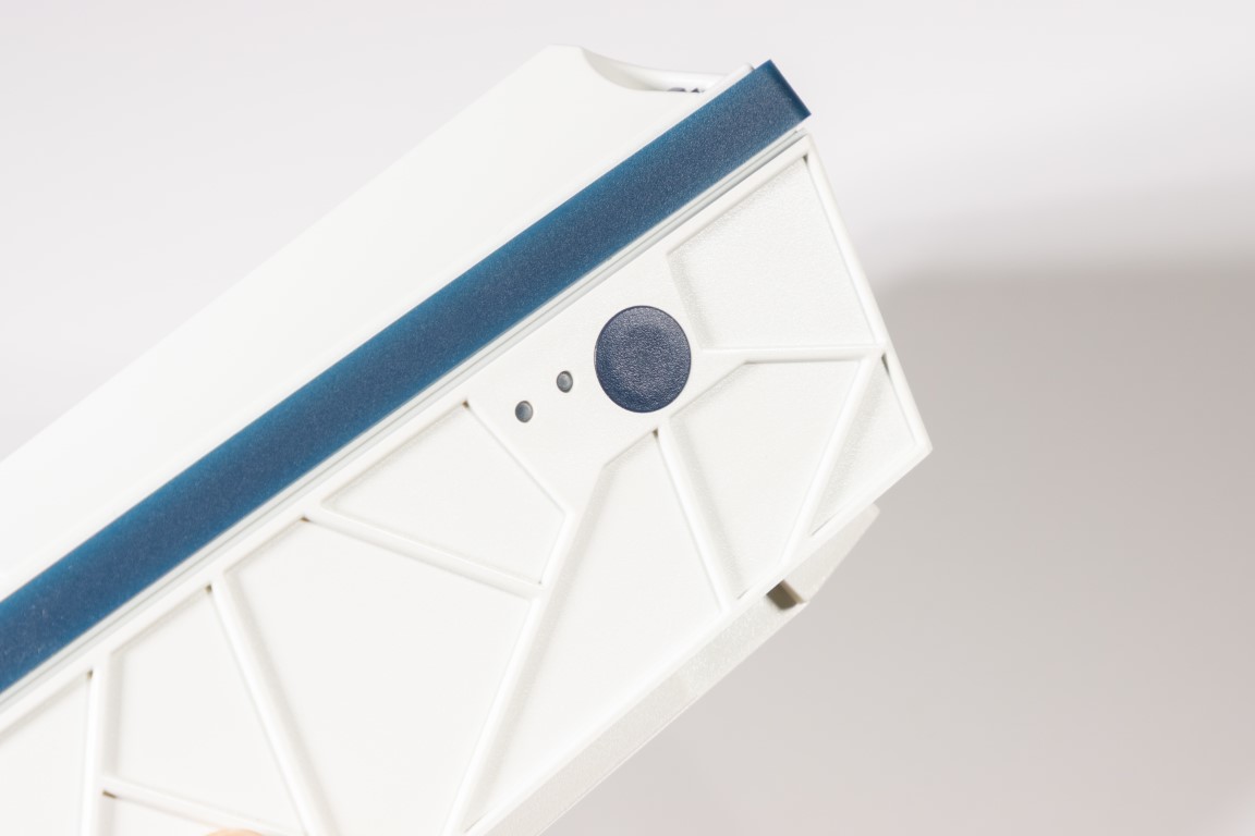
2. Connecting the External Button
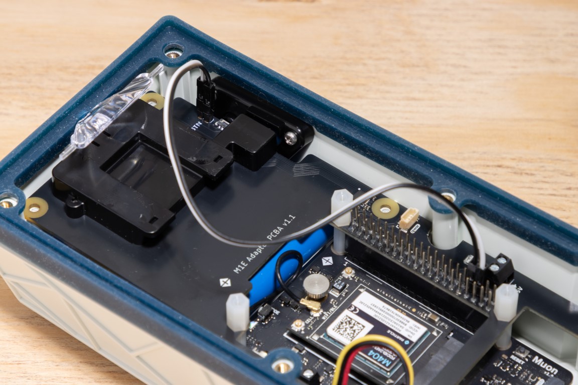
The M1 enclosure includes a user-accessible push button on the exterior. You can hook it up to any of Muon's GPIOs and enable wake/sleep actions or emulate the MODE button.
The BTN header is clearly marked, has no polarity, and is easy to connect.
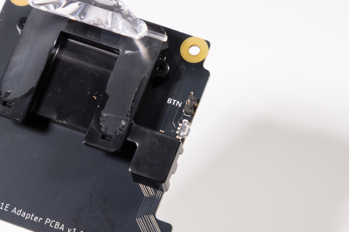
Use two jumper wires included in your M1 kit (colors might differ) to connect the BTN header to any of the Muon's GPIO's and GND pins. In the following example we have connected one of the button pins to Muon's GPIO16 (pin36) and the other pin to GND (pin 34). You'll need to configure this GPIO as an INPUT with the internal pull-up resistor enabled.
We recommend using 6" female-to-female dupont jumper wires.
3. Qwiic Interface (a.k.a. STEMMA QT)
We love SparkFun's Qwiic and Adafruit’s STEMMA QT ecosystems—they make adding I²C peripherals painless.
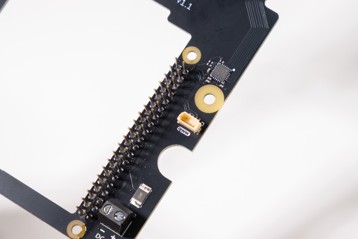
Just plug in compatible sensors, displays, or IMUs—no soldering required. The Qwiic port is tied to pins 3 and 5 on the Muon's header and runs at 3.3V logic.
🧱 Mounting the Enclosure
You’ll find detailed mounting patterns and mechanical specs in the datasheet.
Perfect for wall plates, custom brackets, or even pole mounts.
🔗 View Mounting Instructions →
📄 M1 Enclosure Datasheet
Need technical drawings, environmental ratings, or compliance info?
Check out the full M1 datasheet →