Camera Support on Tachyon
Whether you're building a computer vision app, doing edge AI inference, or just want to stream live video, Tachyon has you covered with dual MIPI CSI support.
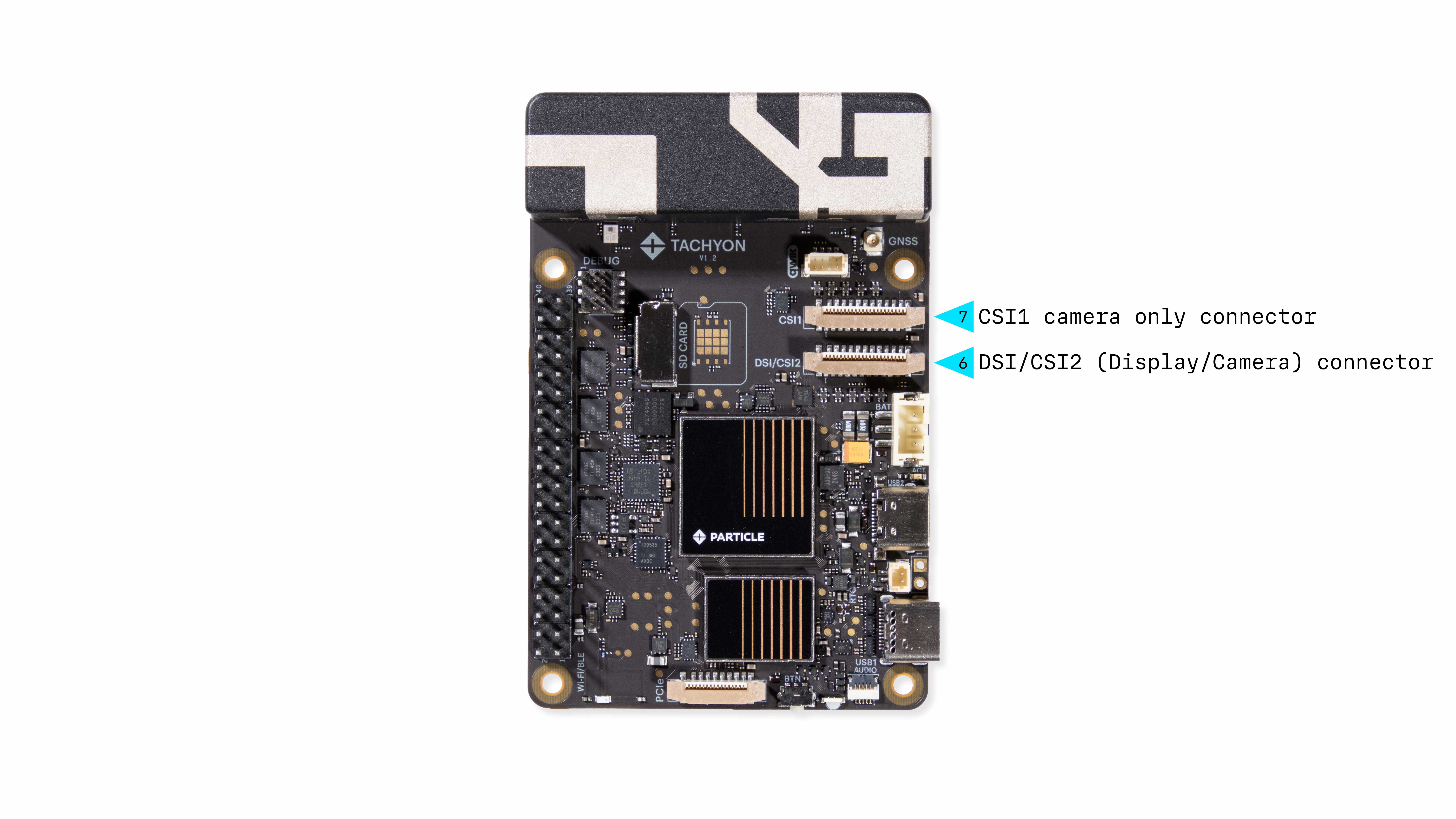
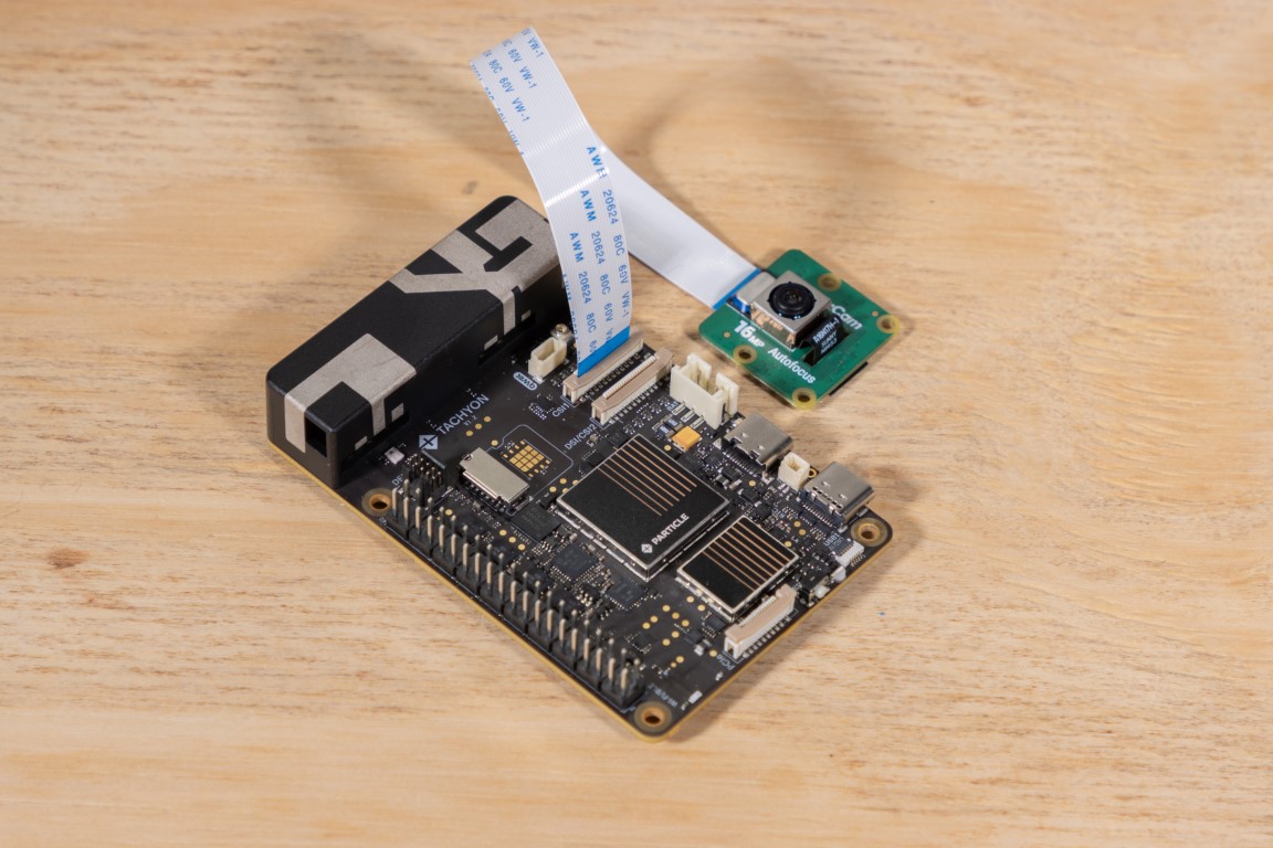
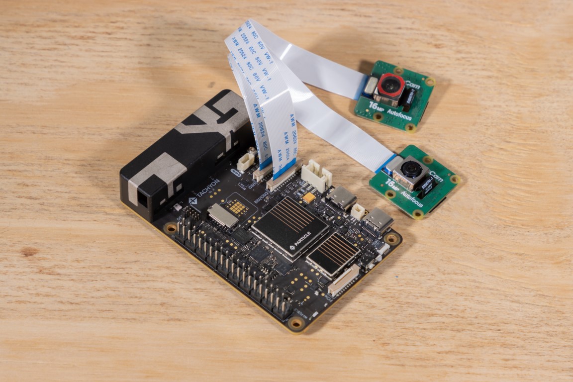
Out of the box, Tachyon can connect up to two MIPI camera modules simultaneously. It includes:
- One dedicated CSI connector
- One flexible DSI/CSI combo connector, which can be configured in software
This gives you flexible configuration options:
- 1 camera + 1 display, or
- 2 cameras at the same time
These connectors follow the Raspberry Pi CAM/DISP mechanical and electrical interface standards, meaning the pinout and cable types are compatible. However, Raspberry Pi camera modules are not yet supported, as they require a closed-source firmware stack. We're actively working on expanding compatibility with popular camera modules and will provide updates as support improves.
Use cases include:
- 📸 Real-time image capture and ML model inference
- 🤖 Stereo vision for robotics
- 🧪 Scientific imaging or time-lapse projects
- 🖥️ Display + camera combos for user-facing interfaces
CSI Specs
Tachyon’s CSI connectors are 4-lane MIPI CSI interfaces, running at speeds of up to 2.5 Gbps per lane. That’s plenty of bandwidth for most camera modules out there.
- Connector type: 22-pin, 0.5 mm pitch FPC cable
- Speed: Up to 2.5 Gbps/lane
- Lanes: 4 per connector
Just plug in a compatible MIPI camera and start capturing high-speed, high-res video streams!
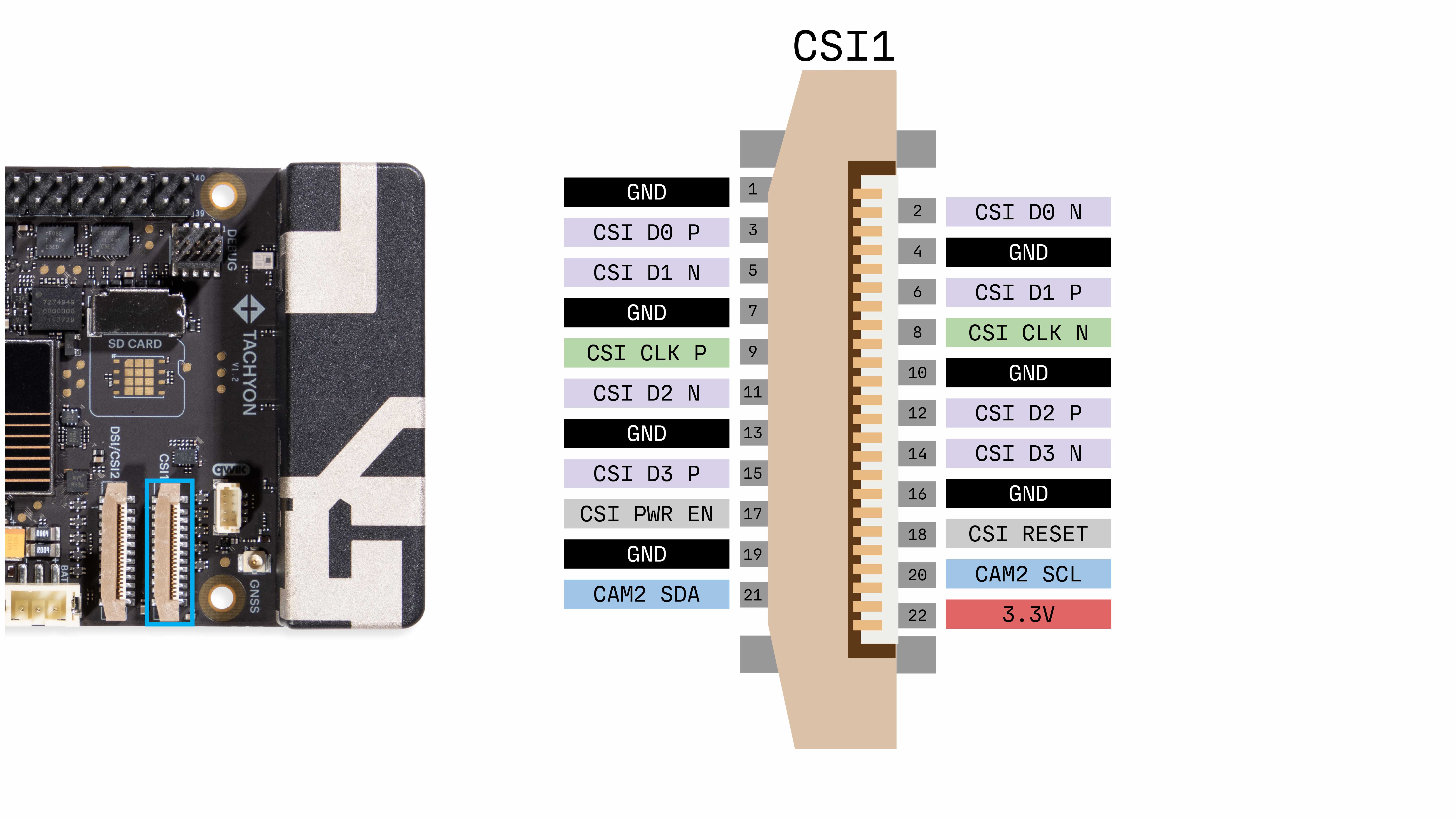
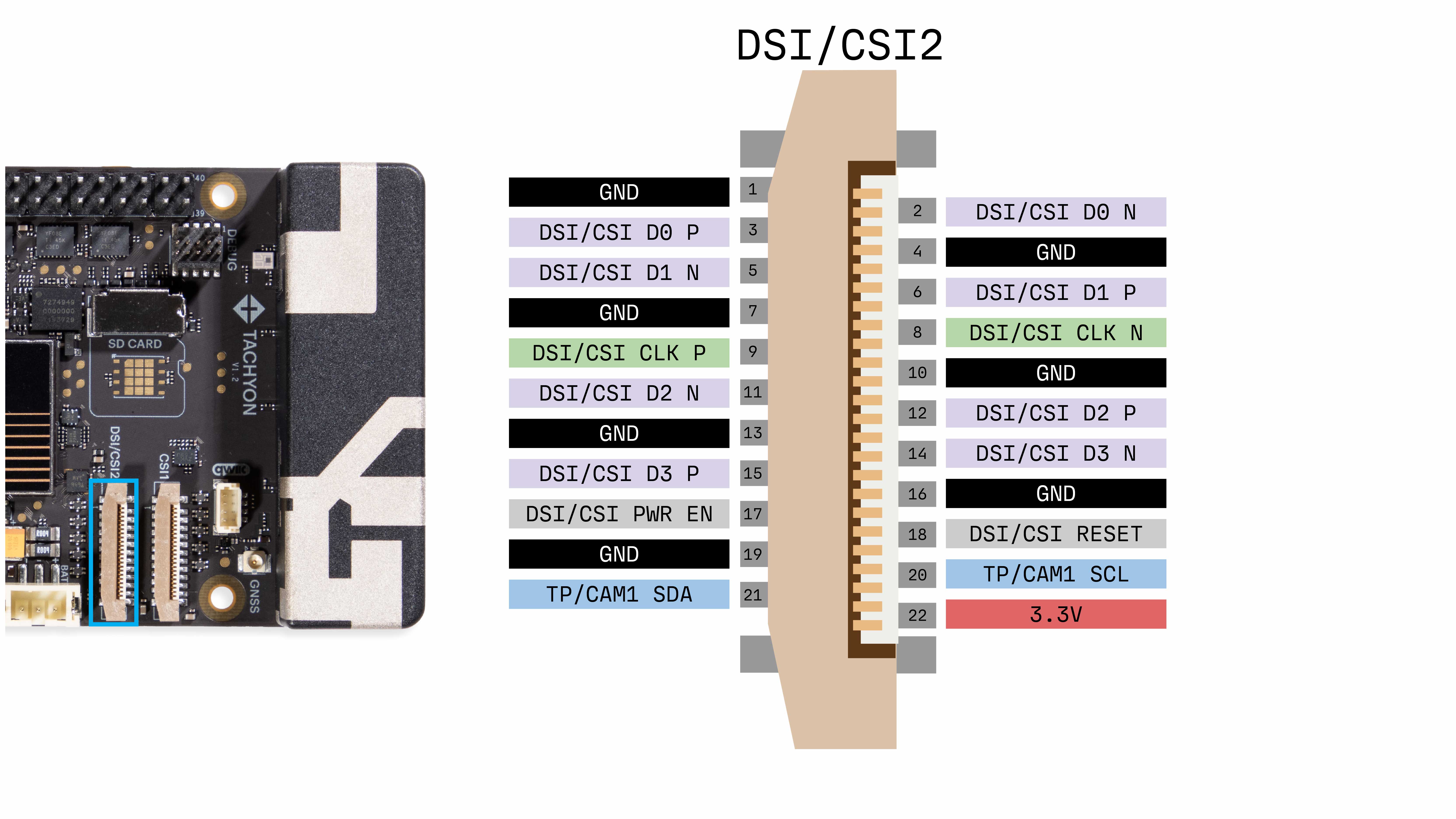
CSI Connector Pinout
📷 Supported Cameras
Tachyon currently supports the following camera modules:
- Samsung S5K3P9SX
- Sony IMX519 Autofocus Module
These modules connect via the CSI interface and are supported out of the box.
Want to try a different camera?
Check out the QCM6490 camera compatibility list.
Many additional models are electrically compatible, but may require driver integration and testing.
Tachyon uses a 22-pin, 0.5mm pitch CSI/DSI connector.
This is not compatible with the older 15-pin Raspberry Pi camera cables.
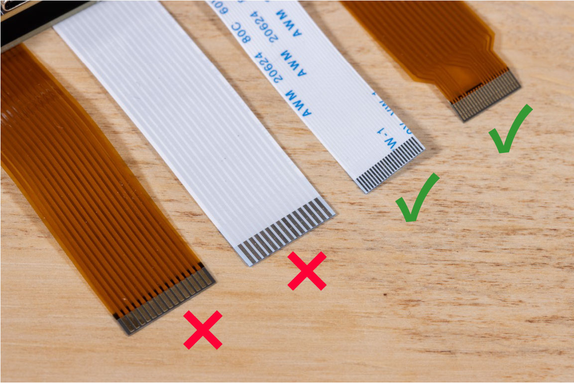
Make sure to use the correct cable that came with your camera module or the Tachyon kit.
Hardware Setup
Connecting your CSI camera is easy—just follow these steps carefully.
1. Open the Connector
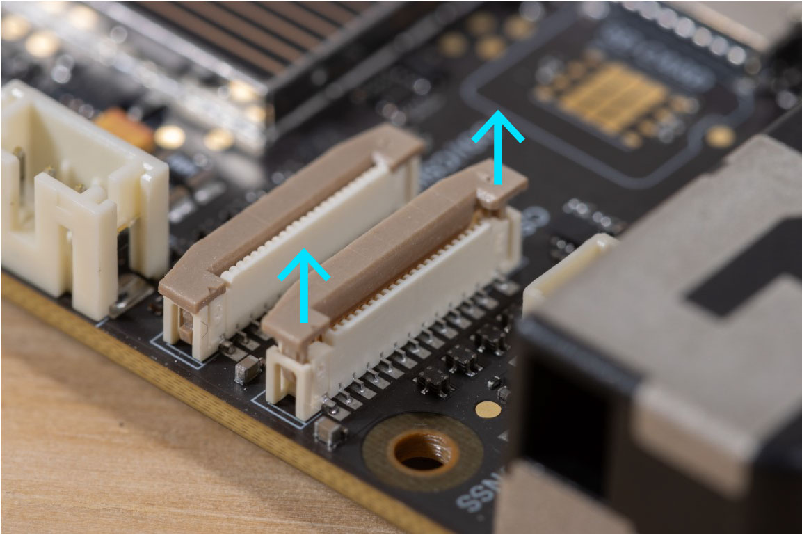
Lift the plastic retention tab on the CSI connector. Be gentle—it’s hinged and shouldn't be pulled off.
2. Insert the Cable
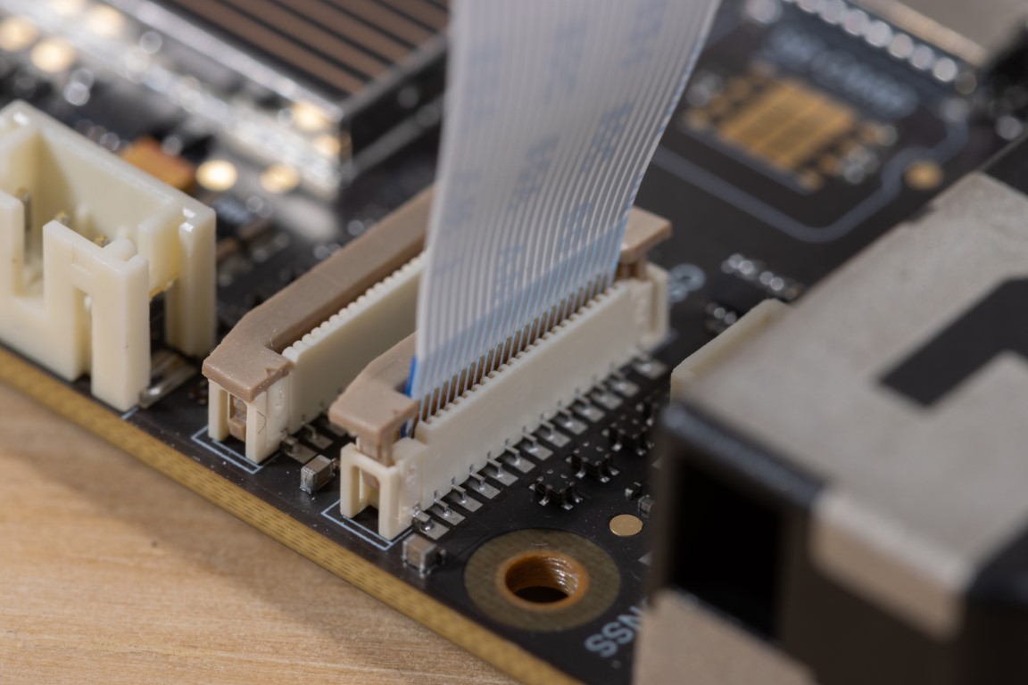
Insert the FPC cable with the metal contacts facing away from the retention tab.
3. Lock It In

Push the tab back down to secure the cable. It should click into place and hold the cable snug.
4. Confirm Orientation
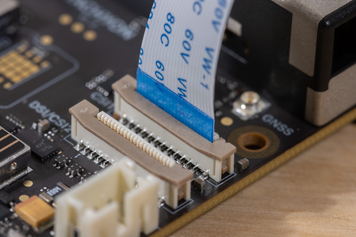
The blue (insulated) side of the ribbon cable should face toward the tab as shown above.
✅ That’s it! Your camera is now physically connected.
Follow the software setup guide next to start capturing video or stills.
Dual Camera Configuration
Tachyon supports dual camera use by toggling the shared CSI/DSI connector using an onboard MIPI switch.
This switch allows you to dynamically enable either CSI or DSI mode via GPIO 68.
- Default: DSI mode
- To enable CSI mode, set GPIO 68 to HIGH:
gpio.sh set 68 out 1
Camera Software
Video and still images can be recorded from the cameras using GStream and the included Qualcomm MultiMedia Framework (qtiqmmfsrc) plugin. The plugin works with the Qualcomm Media Framework to output the desired media pipeline.
More details about the available plugins can be found in the Qualcomm documentation
Check the supported capabilities of the plugin using
gst-inspect-1.0 qtiqmmfsrc
Gstream pipelines are generally created with gst-launch-1.0 -e qtiqmmfsrc camera=0.
camera=0 uses the camera connected to the CSI1 connector.
camera=1 uses the camera connected to the DSI/CSI2 connector.
There are many ways to transform the pipeline, see the gstream documentation or experiment with different options
export XDG_RUNTIME_DIR=/run/user/root
Additionally, all pipelines need to be run as root or under sudo. Or you can add your user to the video group:
$ sudo usermod -a -G video <username>
Capturing Still Pictures
Example: Capture a 1920x1080 image at 30 FPS using the CSI1 camera. Control-C to stop the pipeline and write the last recorded image to the file location specified
gst-launch-1.0 -e qtiqmmfsrc camera=0 \
! video/x-raw,format=NV12,width=1920,height=1080,framerate=30/1 \
! jpegenc \
! multifilesink location=/home/particle/snapshot.jpg
Capturing Video
Example: Capture a 1920x1080 video at 30 fps, using CSI1 camera, recording to the output file location
gst-launch-1.0 -e qtiqmmfsrc camera=0 \
! video/x-raw,format=NV12,width=1920,height=1080,framerate=30/1 \
! qtic2venc ! h264parse ! mp4mux ! queue \
! filesink location=/home/particle/video_snapshot.mp4
Streaming Video
Example: Stream the CSI camera output to a new window in the GNOME desktop environment
gst-launch-1.0 -e qtiqmmfsrc camera=0 ! video/x-raw ! videoconvert ! autovideosink
Using Qualcomm AI Engine with Video Pipelines
If you have existing Raspberry Pi object detection code (e.g., TensorFlow, PyTorch, or OpenCV-based), you can adapt it to leverage the Qualcomm AI Engine (CPU/GPU/NPU) on Tachyon. This enables hardware-accelerated inference and optimized video encode/decode for better performance.
Why Use MJPG Instead of NV12?
Some V4L2 devices or drivers may not fully support the NV12 pixel format for encoding. Using MJPG (Motion JPEG) improves compatibility across a wider range of cameras and pipelines, ensuring stable frame capture and encoding.
1. Hardware Video Encode Pipeline
Tachyon’s QCM6490 SoC includes the Venus hardware video encoder, accessible through V4L2 or GStreamer.
Goal: Encode raw video (e.g., YUV frames) to H.264/H.265 using hardware.
Tools:
v4l2-ctlffmpegorGStreamer/dev/videoXnodes (check which support encoding)
CLI Example:
This example assumes a Logitech USB webcam connected to the device. Your camera may appear at a different /dev/videoX node, so adjust the examples as needed. You can also use a CSI camera connected to the dedicated camera interface.
v4l2-ctl --device=/dev/video2 \
  --set-fmt-video=width=1920,height=1080,pixelformat=MJPG
v4l2-ctl --stream-mmap --stream-count=300 --stream-to=out.h264
Python Example (OpenCV + V4L2 backend):
import cv2

cap = cv2.VideoCapture('/dev/video2')  # V4L2 encoder node
out = cv2.VideoWriter('encoded.h264', cv2.VideoWriter_fourcc(*'H264'), 30, (1920, 1080))

while cap.isOpened():
    ret, frame = cap.read()
    if not ret:
        break
    out.write(frame)

cap.release()
out.release()
2. Hardware Video Decode Pipeline
Goal: Decode H.264 or H.265 video using hardware acceleration.
GStreamer CLI Example:
gst-launch-1.0 filesrc location=input.h264 ! h264parse ! v4l2h264dec ! autovideosink
Python GStreamer Example:
import gi
gi.require_version('Gst', '1.0')
from gi.repository import Gst

Gst.init(None)
pipeline = Gst.parse_launch("filesrc location=input.h264 ! h264parse ! v4l2h264dec ! autovideosink")
pipeline.set_state(Gst.State.PLAYING)
3. Camera GStreamer Pipeline (ISP + Encode/Decode)
Goal: Capture camera input, apply ISP (auto white balance, exposure), encode it, then decode and display.
GStreamer CLI Example:
gst-launch-1.0 \
v4l2src device=/dev/video0 ! video/x-raw,width=1280,height=720,format=MJPG ! \
v4l2h264enc ! h264parse ! v4l2h264dec ! autovideosink
This pipeline:
- Captures from camera
- Encodes via hardware
- Decodes via hardware
- Displays the output
4. Running Object Detection on Live Camera
Goal:
- Run a live camera preview.
- Encode video for storage.
- Send frames through an object detection model (e.g., YOLOv5 or MobileNet).
Strategy:
- Use
teein GStreamer to split the camera stream:- Path 1: Inference (appsink to Python/OpenCV + TensorFlow).
- Path 2: Encode and save video.
- Path 3: Decode and display live preview.
GStreamer CLI Example:
gst-launch-1.0 \
v4l2src device=/dev/video0 ! video/x-raw,width=640,height=480,format=MJPG ! tee name=t \
t. ! queue ! v4l2h264enc ! h264parse ! filesink location=recording.h264 \
t. ! queue ! videoconvert ! autovideosink \
t. ! queue ! appsink name=appsink
Python + TensorFlow Example:
import cv2
import numpy as np
import tensorflow as tf  # or tflite_runtime

# Load and prepare your model here (e.g., TensorFlow Lite)
# interpreter = tf.lite.Interpreter(model_path="mobilenet.tflite")
# interpreter.allocate_tensors()

cap = cv2.VideoCapture("appsink")  # Hook into GStreamer appsink

while True:
    ret, frame = cap.read()
    if not ret:
        break

    # Preprocess the frame for inference
    input_frame = cv2.resize(frame, (224, 224))
    input_tensor = np.expand_dims(input_frame, axis=0).astype(np.float32)

    # Run inference
    # interpreter.set_tensor(input_details[0]['index'], input_tensor)
    # interpreter.invoke()
    # output = interpreter.get_tensor(output_details[0]['index'])

    cv2.imshow("Inference View", frame)
    if cv2.waitKey(1) == ord('q'):
        break

cap.release()
cv2.destroyAllWindows()
5. AI Engine Integration (Qualcomm QCM6490)
To leverage the Hexagon DSP/NPU for faster inference, use Qualcomm's:
- QNN SDK or
- SNPE (Snapdragon Neural Processing Engine)
Steps:
- Convert your model (TensorFlow Lite or ONNX) to a format supported by SNPE/QNN.
- Use the SNPE Python or C++ API to run inference on the DSP/NPU.
- Capture frames from the GStreamer pipeline (
appsink) and feed them to the AI engine.
6. Demos and References
- Qualcomm QNN SDK and SNPE documentation provide sample pipelines for object detection.
- Tachyon-specific examples can be built by combining the encode/decode pipelines above with SNPE or TensorFlow Lite.
Note
Currently, we don’t have pre-built object detection demos tailored for Tachyon, but the workflow is:
- Capture frames using V4L2/GStreamer.
- Preprocess frames (resize, normalize).
- Run inference using SNPE/QNN on DSP/NPU.
- Overlay results or forward to encoder.
We plan to provide sample scripts in future releases.
Notes and Caveats
- When using a CSI camera,
/dev/video0and/dev/video1are not V4L2 devices, they are control endpoints for the Qualcomm media framework. - The Qualcomm camera service can be restarted via
systemctl restart qmmf-server.service - If the pipeline fails to open the camera with the error
ERROR: from element /GstPipeline:pipeline0/GstQmmfSrc:qmmf: Failed to Open Camera!, check if there is hanging process using the/dev/videoXdevice (0for CSI1 camera,1for CSI2 camera:)If there is a process holding the device, kill it via# fuser /dev/video1
/dev/video1: 10049Rerun the pipeline and it should succeed.# fuser -k -9 /dev/video1
/dev/video1: 10049 - To include debug output from your Gstream pipeline, append
--gst-debug=*sink:LOG,qtiqmmfsrc:LOGto the end. Include this option on any bug reports