Powering the Tachyon Device
The Tachyon device has several ways to be powered, offering flexibility for different use cases. Here, we’ll explain the three primary methods of powering the device and the considerations for each.
1. USB-C Connector (USB1)
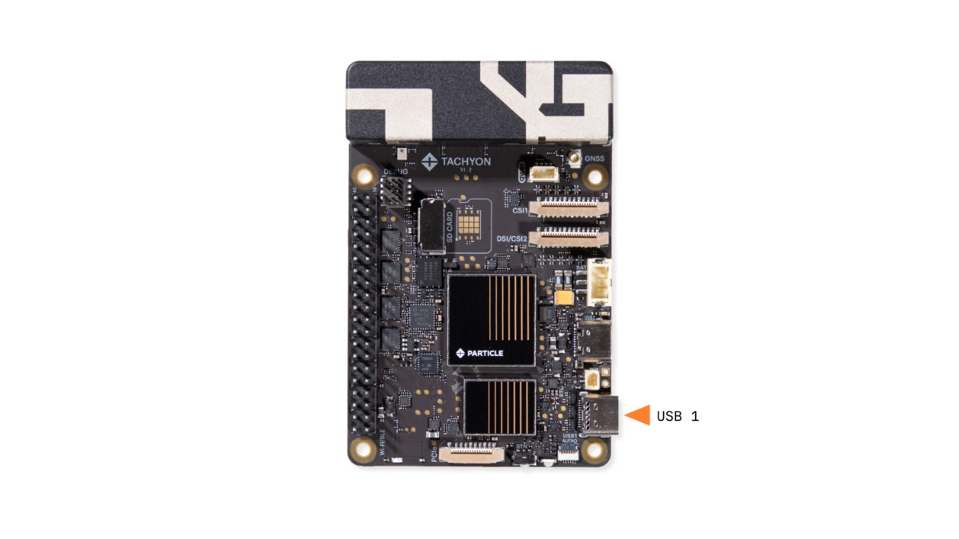
The primary method of powering the device is through the USB-C connector (USB1). This port supports USB 3.1 and is bidirectional, allowing both power and data transfer. This connector can provide power to the device through two key protocols:
- USB Power Delivery (USB PD): Allows for higher voltages and currents, powering the device at up to 3A, 5V, while also enabling simultaneous charging of the device's battery.
- USB 3.1 Power Delivery: Provides standard 5V power via USB 3.1 DP for powering the device and data transfer.
The USB-C port ensures flexibility, and it can be used to power the device while charging the battery at the same time.
2. LiPo Battery (3.7V)
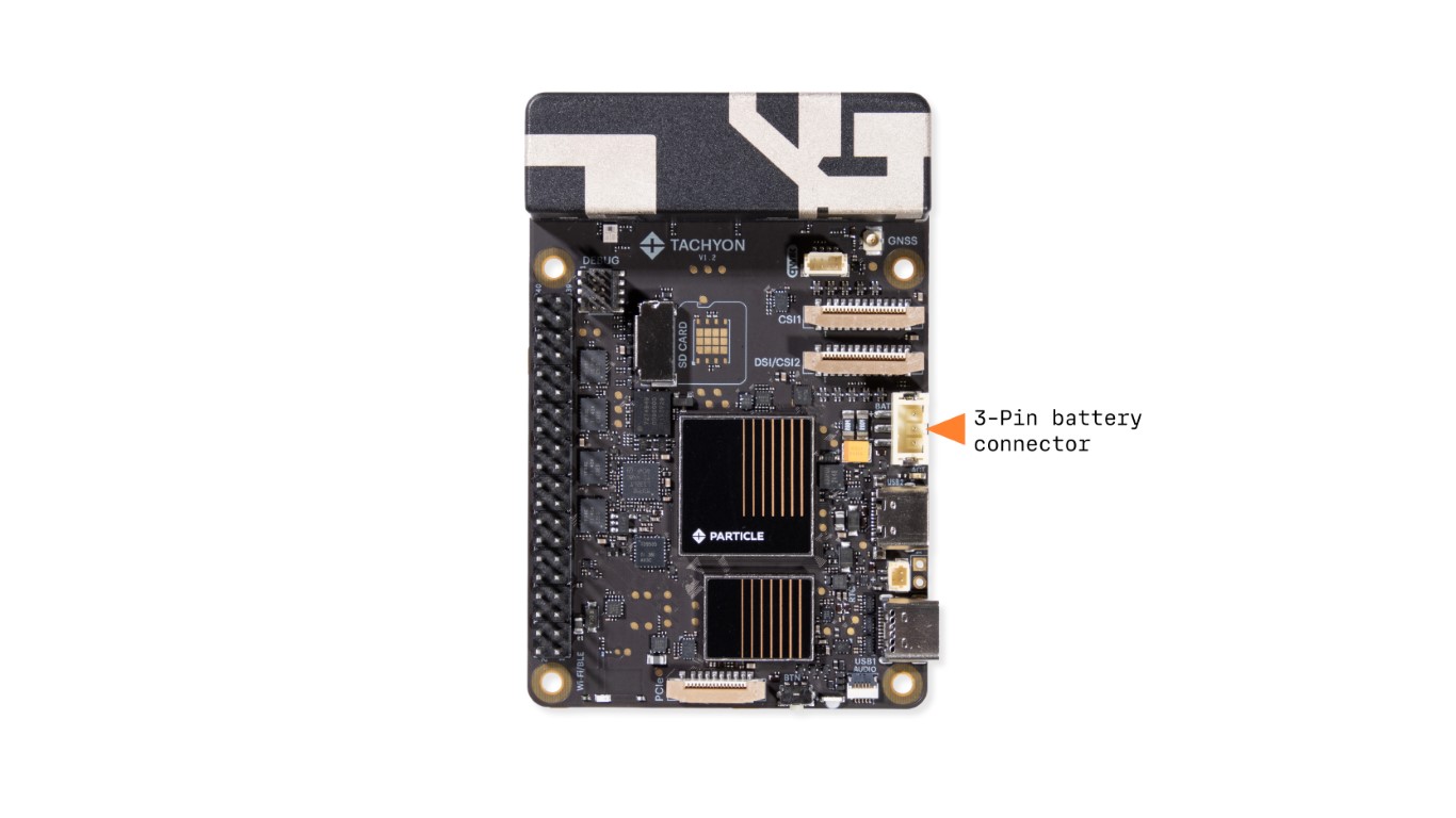
Tachyon can also be powered by a 3.7V LiPo battery, which is supplied by Particle. This battery is designed to fit into the enclosure and provides power when the device is not connected to USB.
Battery Details:
- Battery Type: 3-cell LiPo battery
- Voltage: 3.7V
- Capacity: Sized appropriately for the Tachyon device and enclosures
The battery can be charged through the USB-C port while the device is running. Additionally, the battery is fully mapped and supported by the Tachyon system.
3. 5V Pin Header (40-pin Header)
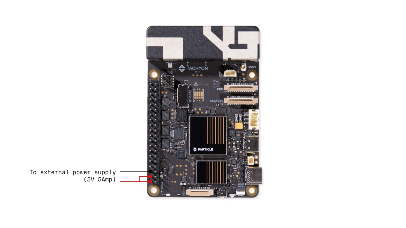
You can also power the Tachyon with an external dedicated 5V power supply connected to the 5V power pin on the 40-pin header. The minimum current requirement is 5A, anything lower and you risk browning out the device.
You can create a split power design where the device remains connected to the battery, but it can also be powered and charged by an external 5V feed, such as from a solar panel or dock. This design is ideal for remote installations where constant power is needed but may come intermittently.
Important Notes:
- ⚠️ Due to the hardware architectural limitations of the device, you'll lose USB 1 functionality when powering from the header.
- Peripherals that consume a lot of current, like motor control HATs, may require an adequate power supply. If not provided, the device may reset or exhibit undesirable behavior.
Low Power Mode
Tachyon is designed to be power-efficient. By default, the SoC does the following:
- Automatically clock gates and ramp down the CPU to minimize power usage when idle. Essentially this lows the clock rate of the CPUs and also disconnects various CPUs from the system if they are not being used.
- Turns on and off peripherals as needed, including the cellular modem, to save energy. This is similar to the clock rate controls - the chip stops the clock (and in some cases removes power) from various parts of the system if its not being used to keep the system in lowpower mode.
Additionally, the onboard LEDs can be controlled via software, allowing them to be turned off to save power if not required.
Microcontroller Power Supervision
The microcontroller inside the Tachyon device manages the power system and ensures the device is properly powered under all conditions. This system controller handles complex power functions and is designed to prevent damage to the device in case of incorrect power management.
Caution:
While the microcontroller is designed to prevent damage, it’s important to ensure that power is managed properly. If the microcontroller is modified outside of the tested path from Particle, it`s possible to damage the board and make the system unrecoverable. By default the system manages the power automatically and you don't need to worry about tweaking this.