PCIe Support on Tachyon
Tachyon comes with one PCIe connector, wired up for a PCIe 3.0 x1 (1-lane) interface. That means you’re getting up to 1 GB/s of theoretical peak bandwidth — enough to power NVMe SSDs, USB expansion hubs, and a variety of other PCIe goodies. No configuration needed — it’s enabled by default. Just plug and play!
Hardware Overview
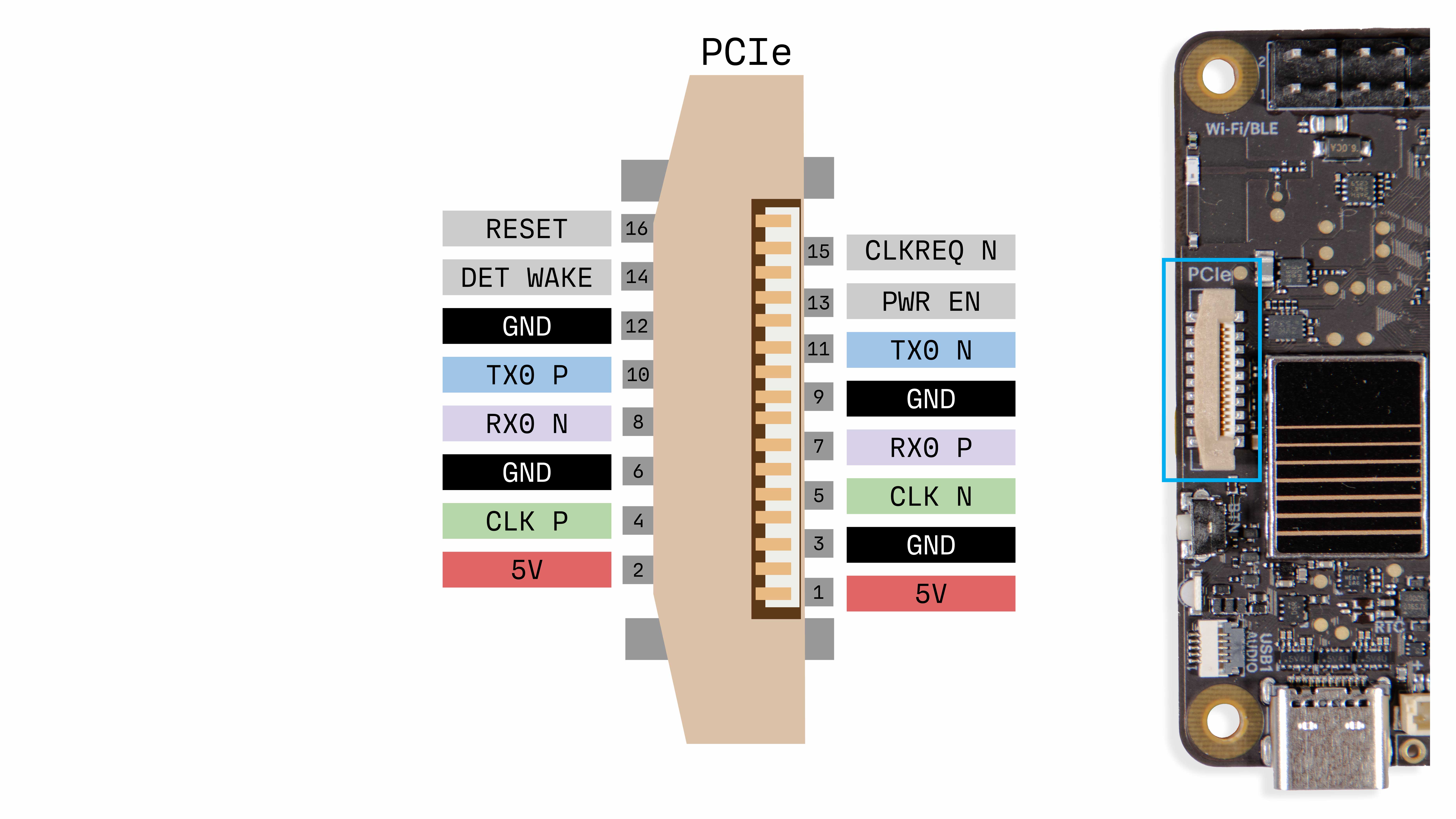
Tachyon is built around the Qualcomm QCM6490 chipset, which actually supports two lanes of PCIe 3.0 under the hood. But to keep things simple — and compatible with the Raspberry Pi PCIe ecosystem — we’re exposing just one lane via the PCIe connector.
There’s a dedicated 5V boost regulator powering the PCIe interface, and it shares that 5V line with the 40-pin header. Why a boost regulator? So that even if Tachyon is running on a 3.7V battery, your PCIe devices still get a clean 5V power supply. 💡
You can also turn PCIe power on or off in software, giving you more control and efficiency in battery-powered projects.
⚡ Power Tip: The maximum current draw is 2A, and that’s shared between the PCIe port and the 5V pin on the 40-pin header. So if you’re using both a HAT and a PCIe peripheral, double-check their combined draw — make sure it stays well below that 2A limit!
PCIe Connector Pinout
Hardware Setup
Connecting PCIe Devices
Tachyon includes a dedicated PCIe interface via an FPC (Flat Printed Cable) connector, allowing you to hook up high-speed peripherals like NVMe SSDs, AI accelerators, or custom boards.
In this guide, we’ll walk through connecting a PCIe NVMe HAT as an example.
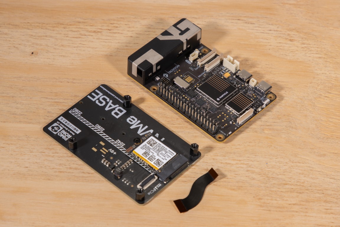
Start with the PCIe NVMe HAT ready and the FPC cable included in your NVMe kit.
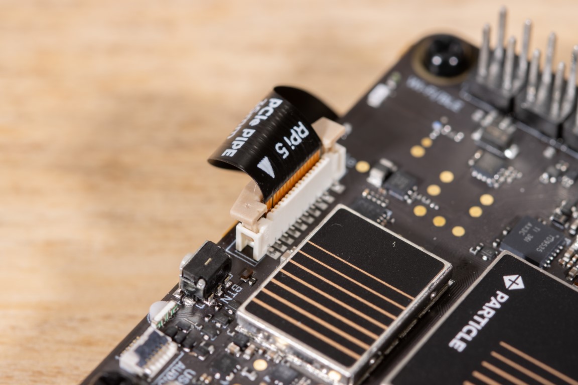
Step 1: Open the Retention Clip
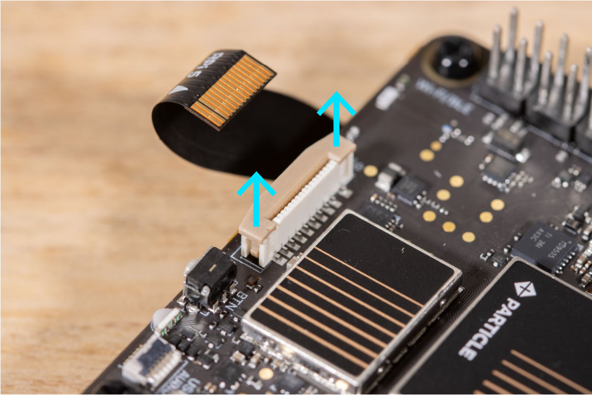
Gently lift the retention clip on the FPC connector. Avoid forcing it—these are delicate.
Step 2: Insert the Cable
Take your FPC cable and insert it into the connector.
✅ Make sure the pin contacts are facing away from the clip (typically down toward the PCB).
Gently push the cable in until it’s fully seated.
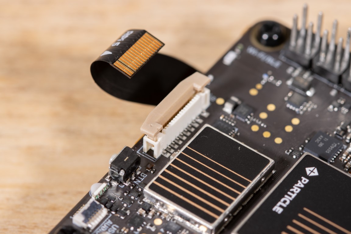
Step 3: Close the Clip
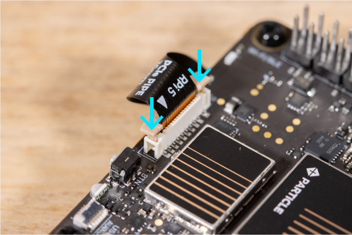
Re-insert the retention clip to lock the cable in place. It should feel firm—not forced.
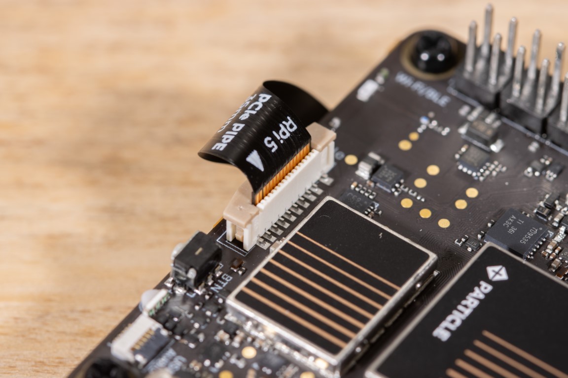
Double-check that the cable is straight and fully seated with the latch properly locked.
Before powering up your Tachyon, always verify the cable orientation on both ends.
Incorrectly connected PCIe cables can damage both the Tachyon and the attached device.
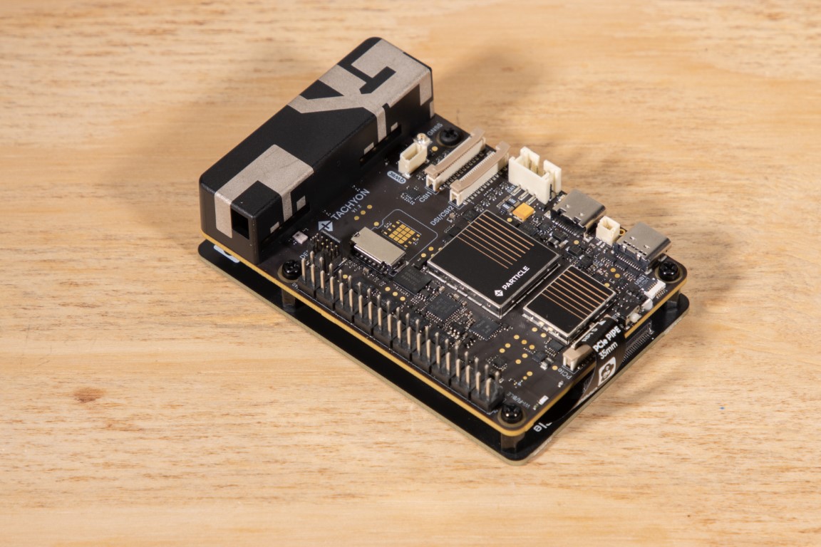
Once connected and secured, your PCIe device should sit flush and aligned. Now you're ready to boot! Power on the Tachyon, the NVMe base Power LED should come on shortly after Tachyon is powered on.
Software setup
-
Examine PCIe devices with
lspcilspci
0000:00:00.0 PCI bridge: Qualcomm Device 010b
0000:01:00.0 Network controller: Qualcomm Device 1103 (rev 01)
0001:00:00.0 PCI bridge: Qualcomm Device 010b
0001:01:00.0 PCI bridge: ASMedia Technology Inc. Device 1182
0001:02:03.0 PCI bridge: ASMedia Technology Inc. Device 1182
0001:02:07.0 PCI bridge: ASMedia Technology Inc. Device 1182
0001:04:00.0 Non-Volatile memory controller: Phison Electronics Corporation Device 5021 (rev 01)PCI bridge 0 is the internal connection to the WiFi/Bluetooth SoC. PCI bridge 1 is the external PCIe connector. Here we can see the NVME controller has been detected.
-
We can see a block device has been created at
/dev/nvme0n1. We can examine it withlsblklsblk | grep nvme0n1
nvme0n1 259:35 0 953.9G 0 disk -
We can format the drive with
fdisk. Generally the options arenfor new partition,pfor primary partition, defaults for sector start and end, and finallywto write and quit.sudo fdisk /dev/nvme0n1
[sudo] password for particle:
Welcome to fdisk (util-linux 2.34).
Changes will remain in memory only, until you decide to write them.
Be careful before using the write command.
Device does not contain a recognized partition table.
Created a new DOS disklabel with disk identifier 0x06a8f583.
Command (m for help): n
Partition type
p primary (0 primary, 0 extended, 4 free)
e extended (container for logical partitions)
Select (default p): p
Partition number (1-4, default 1): 1
First sector (2048-2000409263, default 2048): 2048
Last sector, +/-sectors or +/-size{K,M,G,T,P} (2048-2000409263, default 2000409263): 2000409263
Created a new partition 1 of type 'Linux' and of size 953.9 GiB.
Command (m for help): w
The partition table has been altered.
Calling ioctl() to re-read partition table.
Syncing disks. -
Format the new partition, this may take some time depending on the size of your disk
sudo mkfs.ext4 /dev/nvme0n1
mke2fs 1.45.7 (28-Jan-2021)
Found a dos partition table in /dev/nvme0n1
Proceed anyway? (y,N) y
Discarding device blocks: done
Creating filesystem with 250051158 4k blocks and 62513152 inodes
Filesystem UUID: 5520786a-782e-4715-9165-3334f4f0f931
Superblock backups stored on blocks:
32768, 98304, 163840, 229376, 294912, 819200, 884736, 1605632, 2654208,
4096000, 7962624, 11239424, 20480000, 23887872, 71663616, 78675968,
102400000, 214990848
Allocating group tables: done
Writing inode tables: done
Creating journal (262144 blocks):
done
Writing superblocks and filesystem accounting information: done -
Mount the new partition
sudo mount /dev/nvme0n1 /mnt/The NVMe drive is now available for use
lsblk | grep nvme0n1
nvme0n1 259:35 0 953.9G 0 disk /mnt
Troubleshooting
Forcing Bus Re-enumeration
To force scanning of the PCIe root complex in order to detect new devices
echo 1 > /sys/bus/pci/rescan
Drive Write Testing
Drive write speed can be tested with the dd utility
sudo dd if=/dev/zero of=/mnt/test.bin bs=4k iflag=fullblock,count_bytes count=1G
262144+0 records in
262144+0 records out
1073741824 bytes (1.1 GB, 1.0 GiB) copied, 4.60684 s, 233 MB/s
Supported HATs
NVMe drives and USB hubs generally work without any additional drivers. Some specific boards that have been tested are:
- Pimoroni NVMe Base for Raspberry Pi 5
- Pimoroni NVMe Base Duo for Raspberry Pi 5
- Waveshare PCIe To USB 3.2 Gen1 HAT for Raspberry Pi 5, PCIe to USB HUB
- Waveshare PCIe TO Gigabit ETH Board (C) For Raspberry Pi 5
- 52Pi P02 PCIe Slot for Raspberry Pi 5, Pi 5's PCIe to PCIe x1 slot
- Raspberry Pi M.2 HAT+