Input/Output (GPIO) on Tachyon
Tachyon provides various IO interfaces, including:
- 40-pin GPIO header (compatible with Raspberry Pi HATs)
- Qwiic connector (following SparkFun & Adafruit spec)
40-Pin Header
The 40-pin header follows the Raspberry Pi standard, so most of the HATs designed for RPi should be compatible with Tachyon. We know it`s not perfect, but we want to make sure as many HATs as possible work before the EUFI option to change the pins is made available.
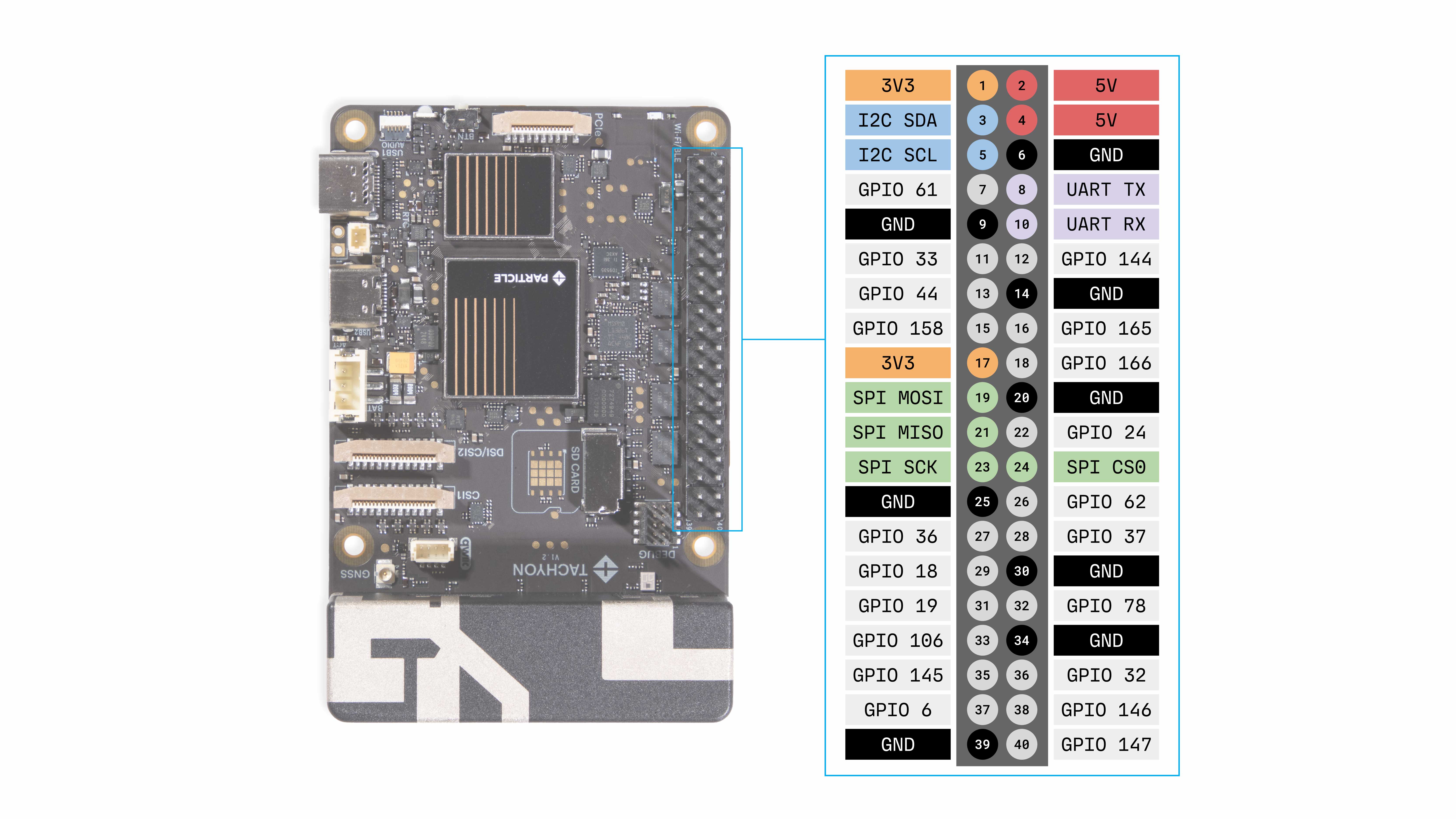
In addition to the primary pin functions, Tachyon also supports a host of alternative functions that are unique this platform. These are listed in the table below.
40-Pin Header GPIO Table
| Pin | GPIO No. | Alternate Function 1 | Alternate Function 2 | Alternate Function 3 |
|---|---|---|---|---|
| 1 | - | 3.3v OUT | - | - |
| 2 | - | 5v IN/OUT | - | - |
| 3 | GPIO_8 | I2C02_SDA | - | - |
| 4 | - | 5v IN/OUT | - | - |
| 5 | GPIO_9 | I2C02_SCL | - | - |
| 6 | - | GND | - | - |
| 7 | GPIO_61 | WAKE* | - | - |
| 8 | GPIO_34 | UART10_TXD | SPI10_CLK | - |
| 9 | - | GND | - | - |
| 10 | GPIO_35 | UART10_RXD | SPI10_CS0 | - |
| 11 | GPIO_33 | UART10_RTS | SPI10_MOSI | I2C10_SCL |
| 12 | GPIO_144 | LPI_MI2S_SCLK | SWR_TX_CLK | - |
| 13 | GPIO_44 | UART13_CTS | SPI13_MISO | I2C13_SDA |
| 14 | - | GND | - | - |
| 15 | GPIO_158 | SWR_TX_DATA2 | - | - |
| 16 | GPIO_165 | LPI_SPI2_SCLK | LPI_UART2_TXD | - |
| 17 | - | 3.3v OUT | - | - |
| 18 | GPIO_166 | LPI_SPI2_CS_0 | LPI_UART2_RXD | - |
| 19 | GPIO_57 | SPI16_MOSI | UART16_RTS | I2C16_SCL |
| 20 | - | GND | - | - |
| 21 | GPIO_56 | SPI16_MISO | UART16_CTS | I2C16_SDA |
| 22 | GPIO_24 | - | - | - |
| 23 | GPIO_58 | SPI16_CLK | UART16_TXD | - |
| 24 | GPIO_59 | SPI16_CS0 | UART16_RXD | - |
| 25 | - | GND | - | - |
| 26 | GPIO_62 | SPI16_CS1 | - | - |
| 27 | GPIO_36 | I2C11_SDA | SPI11_MISO | UART11_CTS |
| 28 | GPIO_37 | I2C11_SCL | SPI11_MOSI | UART11_RTS |
| 29 | GPIO_18 | UART04_TXD | SPI04_CLK | - |
| 30 | - | GND | - | - |
| 31 | GPIO_19 | UART04_RXD | SPI04_CS0 | - |
| 32 | GPIO_78 | PWM2 | - | - |
| 33 | GPIO_106 | MI2S1_SCLK | - | - |
| 34 | - | GND | - | - |
| 35 | GPIO_145 | LPI_MI2S_WS | SWR_TX_DATA0 | - |
| 36 | GPIO_32 | UART10_CTS | SPI10_MISO | I2C10_SDA |
| 37 | GPIO_6 | UART01_TXD | - | - |
| 38 | GPIO_146 | LPI_MI2S_DATA0 | SWR_TX_DATA1 | - |
| 39 | GND | - | - | - |
| 40 | GPIO_147 | LPI_MI2S_DATA1 | SWR_RX_CLK | - |
Here is the table in graphical format:
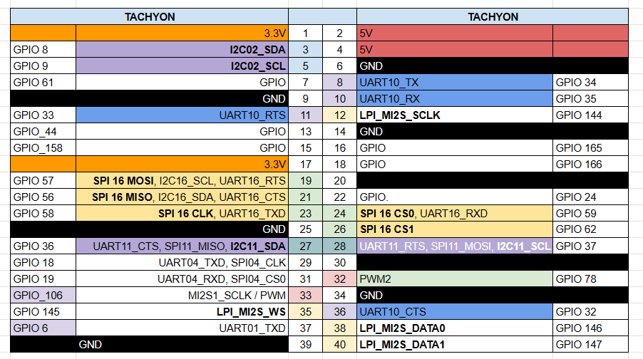
📢 Note: In the initial release, the IOs are fixed to a typical Raspberry Pi HAT configuration.
GPIO
You can test GPIO functionality via the shell using /usr/bin/gpio.sh, a script put together by Particle to help test.
This script is also called at boot to initialize the GPIO and export them so other apps can use them. Cat this script for more info!
cat /usr/bin/gpio.sh
For example, to toggle GPIO_44 (GPIO27 on Raspberry Pi, pin 13), run:
gpio.sh set 44 out 0
Turns off GPIO 44.
gpio.sh set 44 out 1
Turns on GPIO 44.
UART
The Tachyon provides one or more hardware UART interfaces accessible via the 40-pin Raspberry Pi-style HAT header and via the debug connector. These UART interfaces allow you to connect external serial devices, provide console access, or link to sensors, modems, or other peripherals. Note that the I/O levels are 3.3 V only (not 5 V‐tolerant) on the HAT header.
UART Pin Table
| Pin (40-pin header) | GPIO number | UART Function | Notes |
|---|---|---|---|
| Pin 8 | GPIO_34 | UART10_TXD | Alternate function on GPIO_34 |
| Pin 10 | GPIO_35 | UART10_RXD | Alternate function on GPIO_35 |
| Pin 11 | GPIO_33 | UART10_RTS | RTS flow control (optional) |
| Pin 36 | GPIO_32 | UART10_CTS | CTS flow control (optional) |
Note: All GPIO/HAT header I/O is 3.3 V logic. The HAT header is not 5 V tolerant (except the dedicated 5 V power pins).
Specifications
- Logic voltage: 3.3 V TTL-level
- Maximum baud rate: Typically reliable up to 115,200 baud (higher rates may work but are not guaranteed)
- Flow control: Hardware RTS/CTS supported on the alternate pins shown above
- Linux device nodes: UARTs appear as
/dev/ttyHS*(for example/dev/ttyHS2) when enabled - Console/debug UART: Also available via the 10-pin debug connector for system controller and Linux module access
Usage Examples
Note: Use
sudofor all commands unless you are logged in asroot.
Command-Line (Linux Shell)
Without hardware flow control:
sudo apt install minicom   # if not already installed
sudo minicom -D /dev/ttyHS2 -b 115200 -o
With hardware RTS/CTS flow control:
sudo minicom -D /dev/ttyHS2 -b 115200 -o -C
# Inside minicom configuration:
# Serial port → Hardware Flow Control → Yes
Using stty directly:
sudo stty -F /dev/ttyHS2 speed 115200 cs8 -cstopb -parenb -crtscts
Python (Using PySerial)
Tip: Run your Python scripts with
sudoif you are logged in as theparticleuser, e.g.:sudo python3 my_script.py
Without hardware flow control:
import serial

ser = serial.Serial('/dev/ttyHS2', baudrate=115200, timeout=1)
ser.write(b'Hello Tachyon!\r\n')
print(ser.readline())
ser.close()
With hardware RTS/CTS:
import serial

ser = serial.Serial(
    '/dev/ttyHS2',
    baudrate=115200,
    timeout=1,
    rtscts=True
)
ser.write(b'Hello with RTS/CTS\r\n')
print(ser.readline())
ser.close()
SPI (Serial Peripheral Interface)
The Tachyon supports SPI communication through the 40-pin Raspberry Pi–compatible HAT header. The SPI interface allows the Tachyon to communicate with devices such as sensors, flash memory, DACs, or displays using the standard MOSI/MISO/SCLK/CS lines.
All SPI pins operate at 3.3 V logic levels and follow the standard Raspberry Pi pinout for maximum compatibility.
SPI Pin Table
| Pin (40-pin header) | GPIO Number | Function | SPI Role | Notes |
|---|---|---|---|---|
| Pin 19 | GPIO_57 | SPI16_MOSI | Master Out Slave In | Data from Tachyon to device |
| Pin 21 | GPIO_56 | SPI16_MISO | Master In Slave Out | Data from device to Tachyon |
| Pin 23 | GPIO_58 | SPI16_SCLK | Clock | Shared serial clock |
| Pin 24 | GPIO_59 | SPI16_CS0 | Chip Select 0 | Used by /dev/spidev0.0 |
| Pin 26 | GPIO_62 | SPI16_CS1 | Chip Select 1 | Optional (not used in this example) |
Note: SPI logic is 3.3 V only. Do not attach 5 V SPI peripherals directly.
Specifications
- Logic voltage: 3.3 V TTL-level
- Default device node:
/dev/spidev0.0 - SPI mode: 0 (CPOL = 0, CPHA = 0) by default
- Bits per word: 8
- Typical baud rates: Up to 10 MHz (1 MHz safe default)
- Chip select: CS0 (pin 24) driven by Linux driver
Usage Examples
Note: Use
sudofor all commands unless you are logged in asroot.
Command-Line
Check that the SPI device is available
ls /dev/spidev*
Expected output:
/dev/spidev0.0
Send a simple SPI transaction
Install the spi-tools package if needed:
sudo apt install spi-tools
Then, for example, send the byte sequence 0x9F 00 00 00 (commonly used as a “Read JEDEC ID” command on SPI flash chips):
printf '\x9F\x00\x00\x00' | sudo spi-pipe -D /dev/spidev0.0 -s 1000000 -m 0 -b 8 | hexdump -C
-D→ SPI device-s→ speed (1 MHz here)-m→ mode 0-b→ bits per word (8)
You’ll see the response bytes returned from the device on MISO.
Python (Using spidev)
Tip: Run your Python scripts with
sudoif you are logged in as theparticleuser, e.g.:sudo python3 my_spi_script.py
Install the Python library:
sudo apt install python3-pip
sudo pip3 install spidev
Example: Send and receive 4 bytes
import spidev

spi = spidev.SpiDev()
spi.open(0, 0)  # bus 0, device 0 → /dev/spidev0.0
spi.mode = 0
spi.max_speed_hz = 1_000_000

tx = [0x9F, 0x00, 0x00, 0x00]
rx = spi.xfer2(tx)

print("Received:", rx)

spi.close()
Example: Write then read
import spidev

spi = spidev.SpiDev()
spi.open(0, 0)
spi.mode = 0
spi.max_speed_hz = 2_000_000

spi.xfer2([0x9F])                  # Write command
response = spi.xfer2([0x00, 0x00, 0x00])  # Read 3 bytes back
print(response)

spi.close()
I²C (Inter-Integrated Circuit Interface)
The Tachyon provides two I²C (Two-Wire Interface) buses accessible via the 40-pin Raspberry Pi-style HAT header and QWIIC connector. These interfaces allow the Tachyon to communicate with peripheral ICs such as sensors, ADCs, OLED displays, and GPIO expanders using the standard SCL/SDA lines.
All I²C pins operate at 3.3 V logic levels and include internal pull-ups where required, but external pull-ups (typically 4.7 kΩ to 10 kΩ) may still be recommended for certain bus lengths or multiple devices.
I²C Pin Table
| Pin (40-pin header) | GPIO Number | I²C Bus | Function | Notes |
|---|---|---|---|---|
| Pin 3 (P1-03) | GPIO_30 | I2C1_SDA | Data line (SDA) | |
| Pin 5 (P1-05) | GPIO_31 | I2C1_SCL | Clock line (SCL) |
Note: I²C buses are 3.3 V only. Do not connect 5 V I²C devices without proper level shifting.
Specifications
- Logic voltage: 3.3 V TTL-level
- Standard bus speeds:
- 100 kHz (Standard-mode)
- 400 kHz (Fast-mode)
- Possible higher speeds: Up to 1 MHz (Fast-mode Plus), depending on driver and device support
- Linux device nodes:
/dev/i2c-1,/dev/i2c-2, etc. (typically/dev/i2c-1for the primary HAT header bus and/dev/i2c-2for QWIIC connector)
- Pull-ups: Internal pull-ups not present; external 4.7 kΩ may improve stability for long lines or multiple devices
- Voltage tolerance: 3.3 V max on SCL/SDA lines
Usage Examples
Command-Line (Linux Shell)
List available I²C buses
i2cdetect -l
To list all I2C devices connected to the 40-pin header, use:
i2cdetect -y -r 1
Output example:
     0 1 2 3 4 5 6 7 8 9 a b c d e f
00:          -- -- -- -- -- -- -- --
10: -- -- -- 1a -- -- -- -- -- -- --
20: -- -- -- -- -- -- -- -- -- -- --
30: -- -- -- -- -- -- -- -- -- -- --
40: -- 41 -- -- -- -- -- -- -- -- --
Here, devices were found at addresses 0x1A and 0x41.
Read one byte from address 0x41, register 0x00
sudo i2cget -y 1 0x41 0x00
Write a byte (0x01) to address 0x41, register 0x00
sudo i2cset -y 1 0x41 0x00 0x01
Python (Using smbus2)
Install library (if not already):
sudo apt install python3-smbus
Example — read temperature sensor:
import smbus2
import time

bus = smbus2.SMBus(1)  # I2C bus 1 corresponds to pins 3 & 5 on header

I2C_ADDR = 0x41
REG_TEMP = 0x00

while True:
    temp_raw = bus.read_word_data(I2C_ADDR, REG_TEMP)
    temp_c = ((temp_raw & 0xFF) << 8 | (temp_raw >> 8)) / 256.0
    print(f"Temperature: {temp_c:.2f} °C")
    time.sleep(1)
Example — write a register:
bus.write_byte_data(I2C_ADDR, 0x01, 0x10)
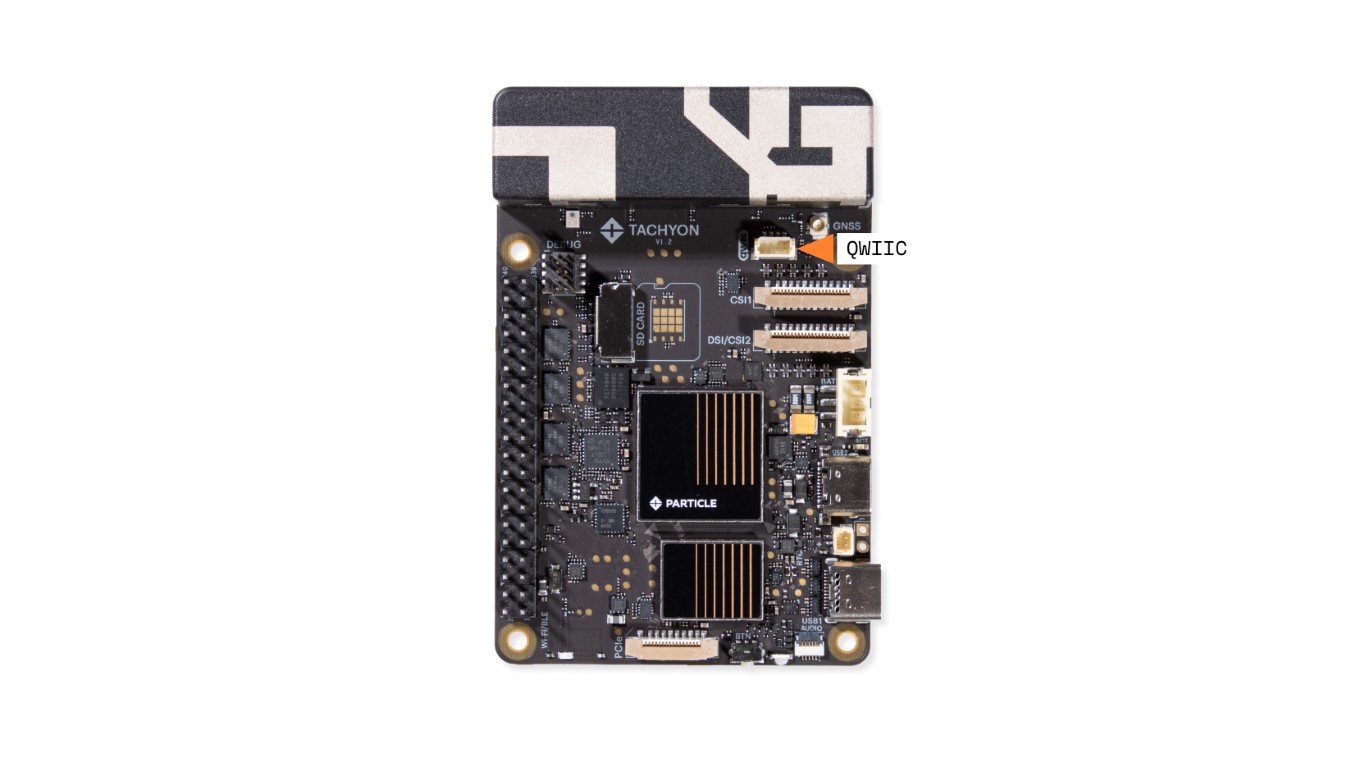
Qwiic Connector (a.k.a. STEMMA QT)
We’re big fans of the SparkFun Qwiic ecosystem (also known as Adafruit’s STEMMA QT) here at Particle. It’s a super convenient way to hook up sensors, displays, and other I²C devices without needing to solder or fuss with wiring. Just plug, chain, and go.
This board includes a dedicated Qwiic connector tied to its own I²C interface running at 3.3V.
Checkout some examples of using the Qwiic interface on this dedicated page here.
To list all I2C devices connected to the Qwiic connector, use:
i2cdetect -y -r 2
⚠️Power note: The Qwiic port is powered from the same 3.3V regulator that feeds other peripherals on the board. That regulator is rated for 1A total, so we recommend keeping your Qwiic chain’s current draw under ~100mA to leave enough headroom for everything else.
WAKE Pin
Tachyon has a special WAKE pin that is multiplexed with GPIO 61 (pin 7 on the 40-pin header). Unlike the rest of the GPIOs on the 40-pin header which are controlled by the Qualcomm module, this pin also is an input to the onboard SysCon MCU. This allows the device to monitor any activity on this pin even when the main module is shutdown. A high going pulse can be used as a trigger to wake the device.
This feature is disabled by default. You can enabled it with the WakePinEnable setting.
Use the following command to list the current settings:
sudo /usr/bin/particle-tachyon-syscon.sh list_config
You should see an output something like this:
Dumping internal raw config:
confVersion = 1
No more keys found

Dumping internal settings (use config to set):
sys.auto_boot: false
sys.wake_pin_enable: false
sys.color_debug_enable: false
sys.fastboot_enabled: false
sys.demo_enabled: false
You can then enable the wake pin feature by using the following command
sudo /usr/bin/particle-tachyon-syscon.sh set_config sys.wake_pin_enable:true
If successful, you should see the following output
Successfully set config: sys.wake_pin_enable:true, rebooting MCU is required to apply changes.
Usage: /usr/bin/particle-tachyon-syscon.sh {local_version|syscon_version|list_config|get_config|set_config|backup_identity|upgrade [--force]}