Hardware Overview
Tachyon is packed with powerful hardware features, all thoughtfully laid out for easy access during development. This section provides an overview of the board’s key connectors, interfaces, and components—helping you quickly identify where everything is and how each part fits into your workflow.
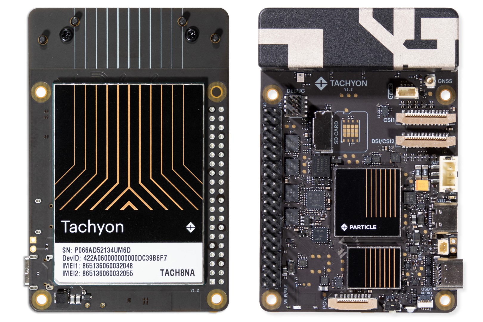
Form Factor
Tachyon follows the Raspberry Pi 5 form factor, keeping familiar connectors like USB-C, LED, button, PCIe, CSI, DSI, and the 40-pin HAT header.
Key updates:
- HDMI ports replaced with a secondary USB 2.0 port and lithium battery connector.
- Ethernet and extra USB ports replaced by a high-speed 5G Sub-6Ghz cellular antenna.
- Optional GNSS antenna support.
- Dedicated audio connector.
- Qwiic accessory support.
Component Layout
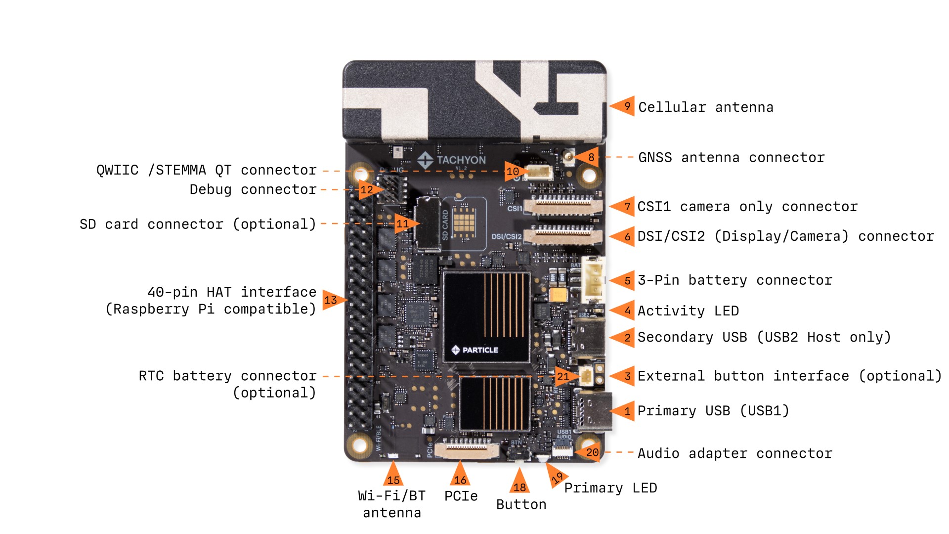
1. Primary USB (USB1)
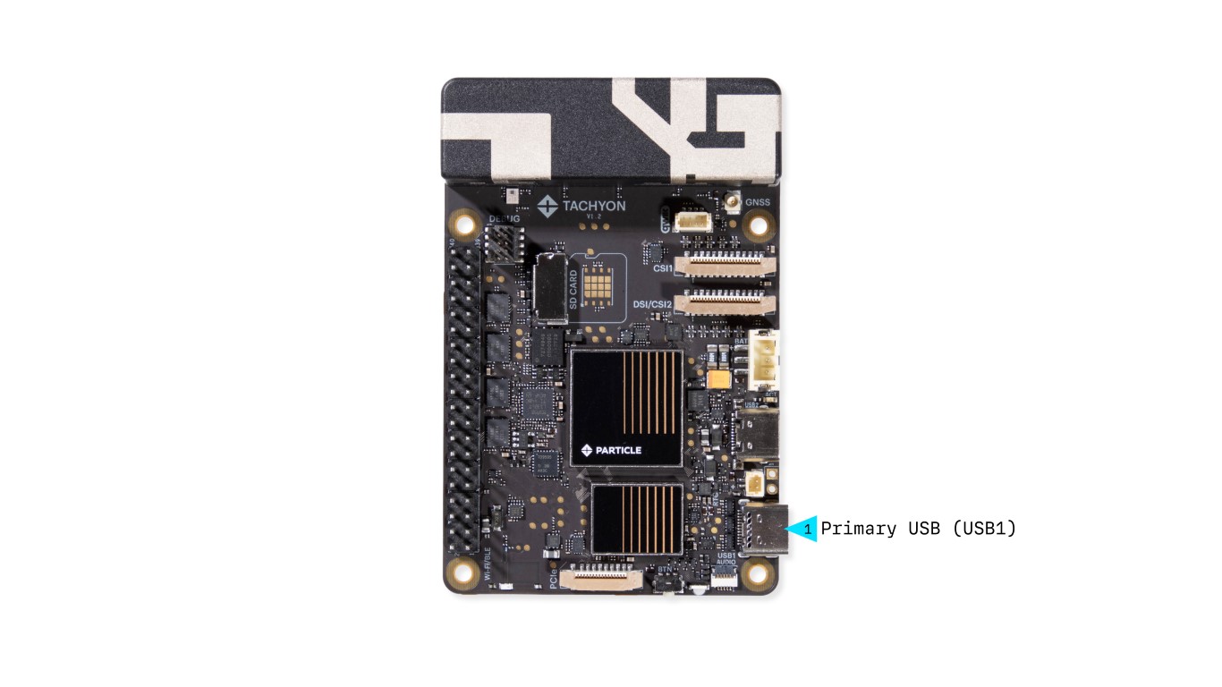
- USB 3.1 bi-directional support
- Power & Data
- Supports USB Power Delivery (PD)
- Can function as host or device, depending on the connection
- Video Output
- Supports USB-C adapters that provide USB + Power + HDMI output
2. Secondary USB (USB2)
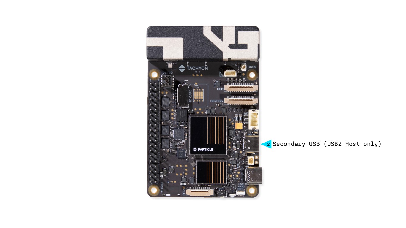
- USB 2.0 Host only
- Standard USB-C port
- Supports USB hubs and provides 5V power to connected peripherals
3. Activity LED
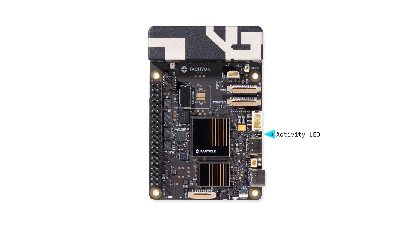
This red Activity LED is wired directly to the Linux processor and is managed by the kernel's activity LED driver.
- By default, it follows preconfigured system parameters chosen by Particle.
- The behavior is user-configurable, allowing developers to override its default settings.
4. LiPo Battery Connector
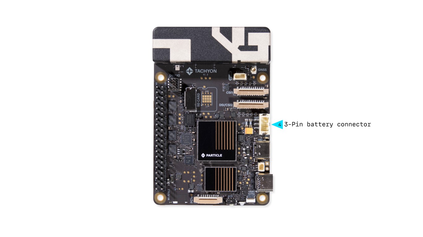
Tachyon supports 3.7V LiPo batteries with a 3-pin JST-PH connector.
- Includes a built-in 10K NTC thermistor for temperature sensing.

📢 Note: Facing the plug on the battery side
5. DSI/CSI2 Display or Camera Connector
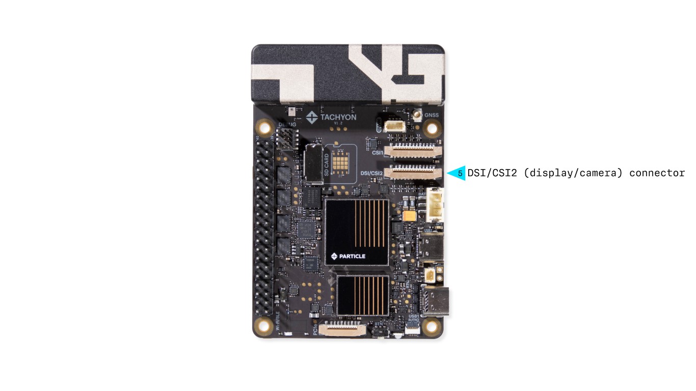
This flexible DSI/CSI combo connector supports a 4-lane MIPI display or camera interface and is functionally and electrically compatible with the Raspberry Pi 5 CAM/DISP connector.
6. CSI1 Camera Connector
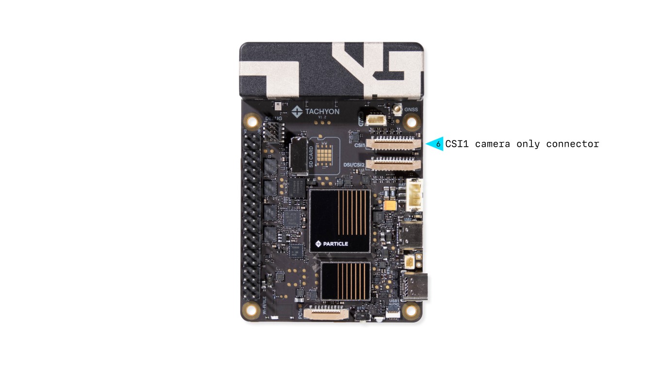
This dedicated 4-lane MIPI CSI connector supports high-speed camera modules with higher resolution and frame rates.
7. GNSS (GPS) Antenna Connector
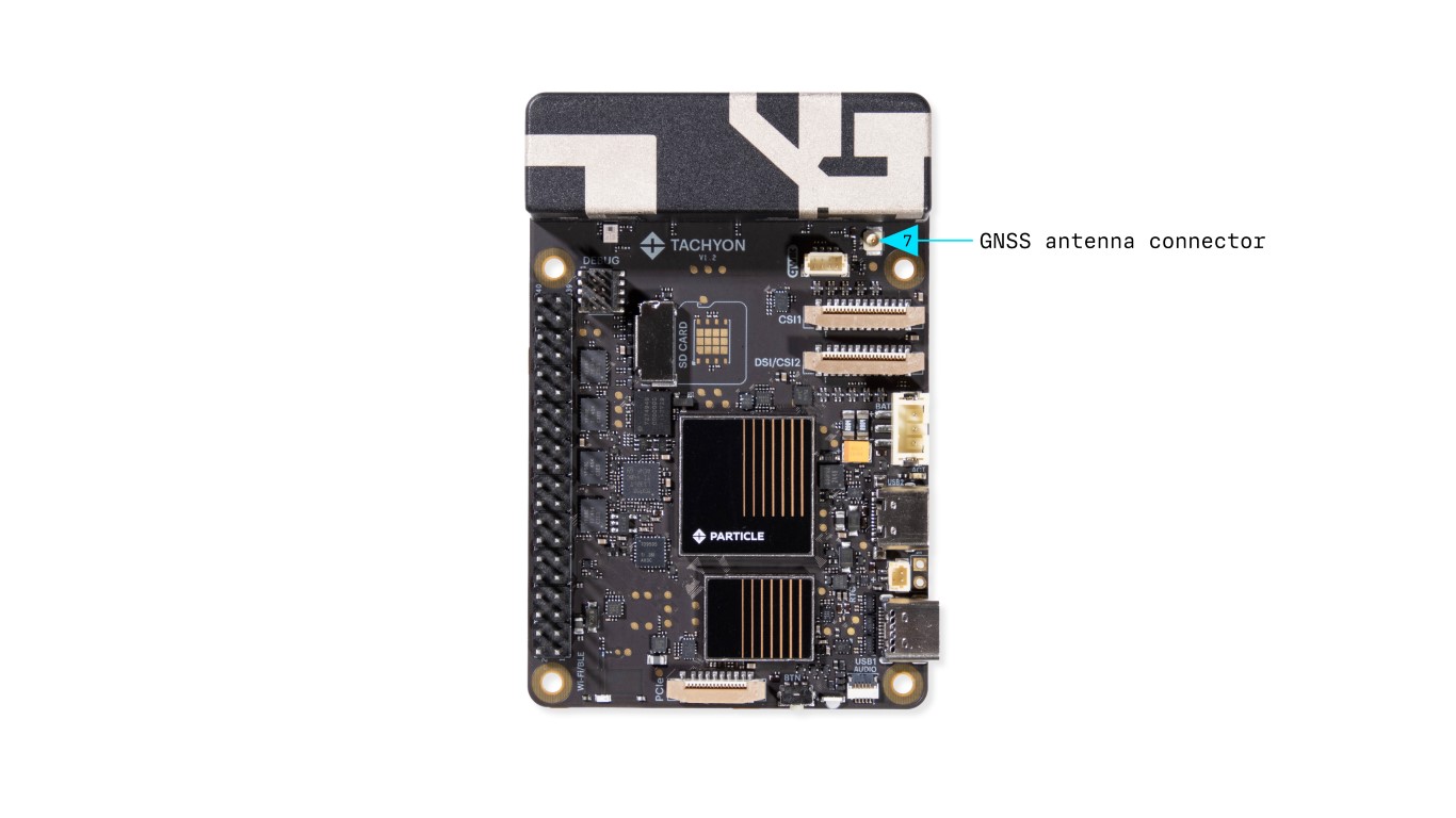
- Antenna is required for GPS functionality
- Compatible with Particle GNSS FPC antenna
For more information on GNSS usage, see the dedicated GNSS section.
8. Cellular Antenna
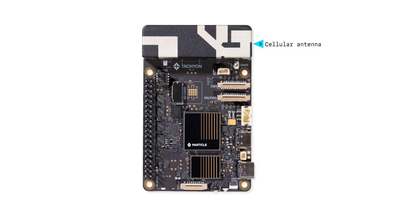
The Tachyon board features a custom high-speed 5G (Sub-6GHz) cellular antenna, directly connected to the onboard modem. This antenna was specifically developed for Tachyon to provide reliable connectivity and optimal performance within its compact design. External antenna support is not currently available, although an internal adapter exists but has not been publicly released.
9. QWIIC Connector
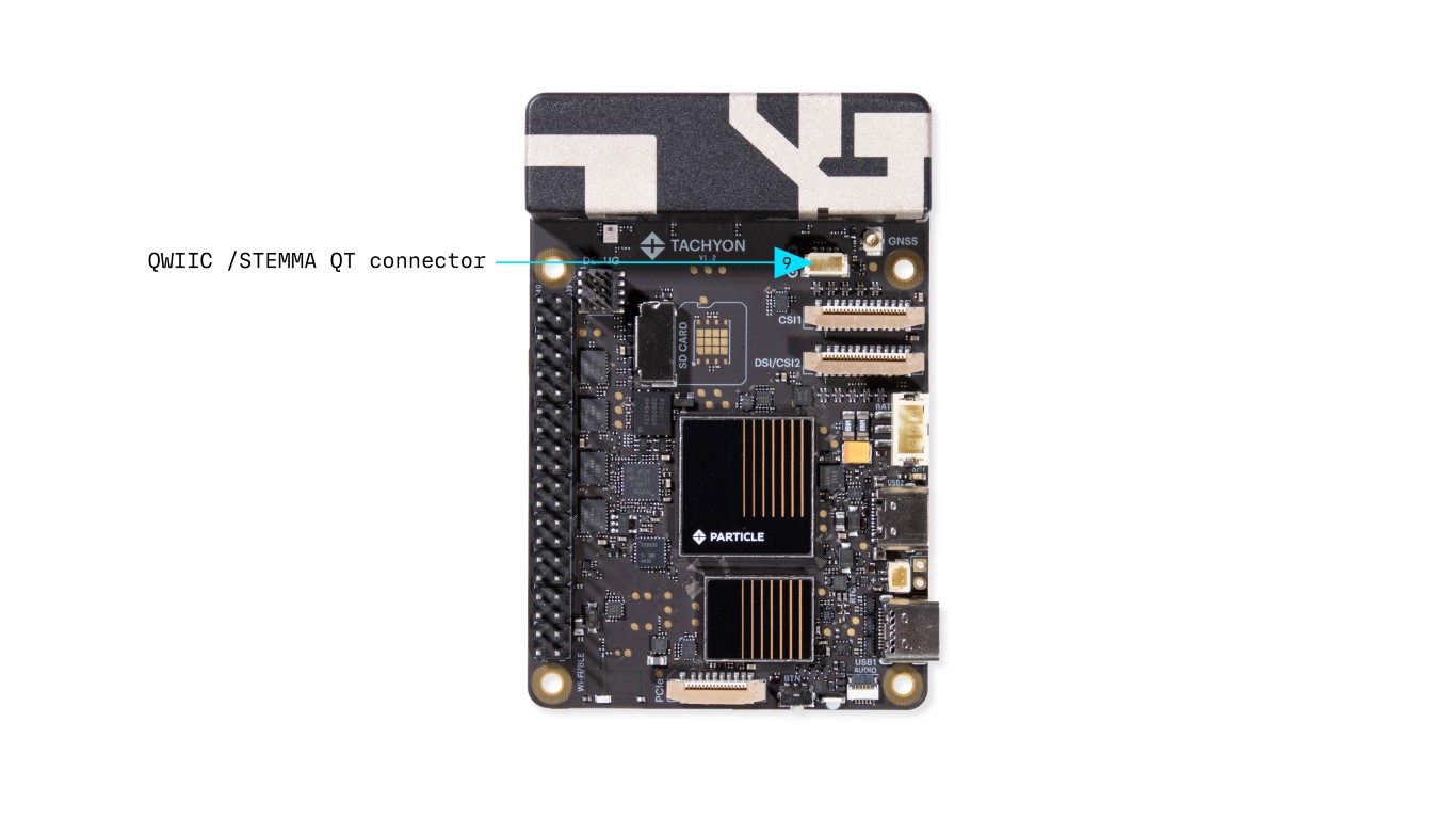
- Follows SparkFun Qwiic / Adafruit STEMMA QT standard
- Enables easy I2C expansion for sensors & peripherals
- Supports daisy-chaining multiple I2C devices
- 4-pin JST 1mm connector (keyed)
More Info: Qwiic Ecosystem
10. Debug Connector
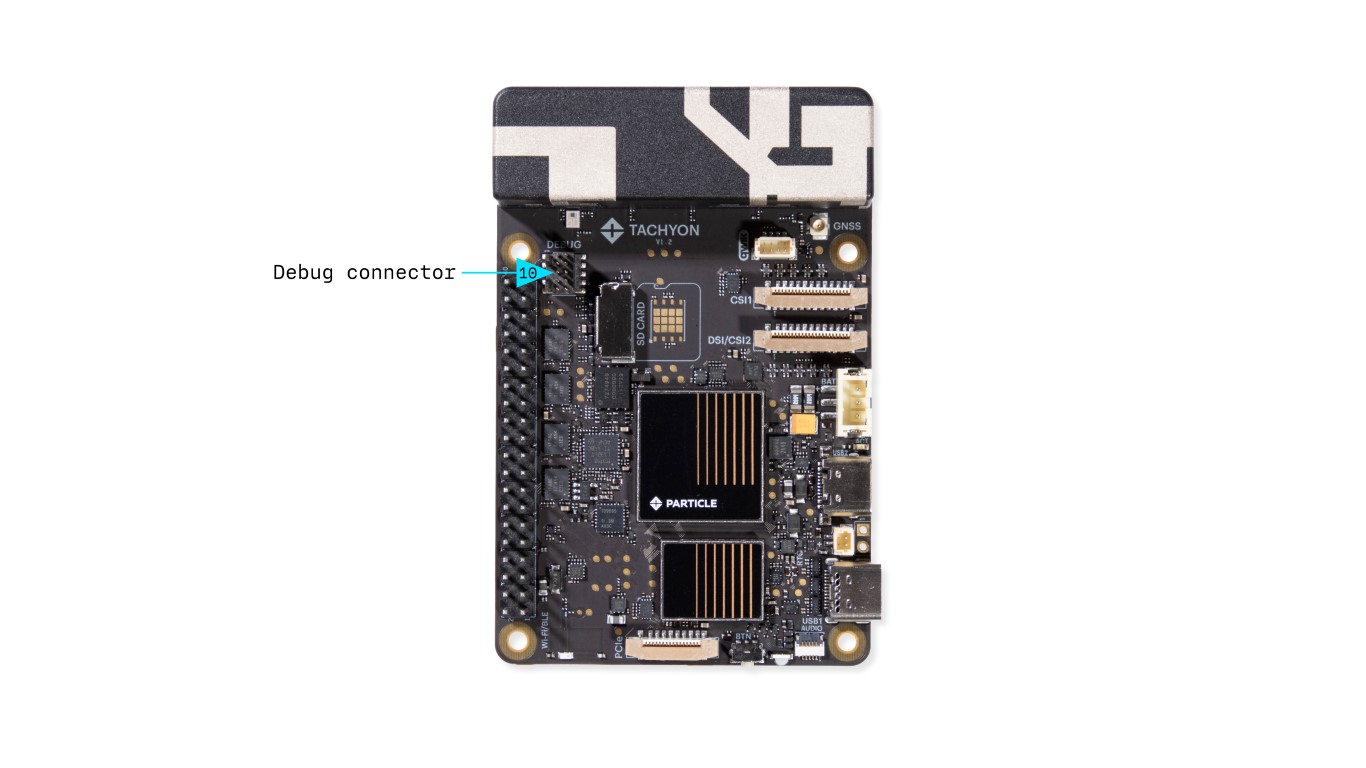
Provides UART access for system debugging.
Used for:
- System Controller (MCU) Debugging
- Linux Module UART Console Access
Connects to the Debug Adapter using a 10-pin (2x5) ribbon cable.
11. SD Card Slot (Optional)
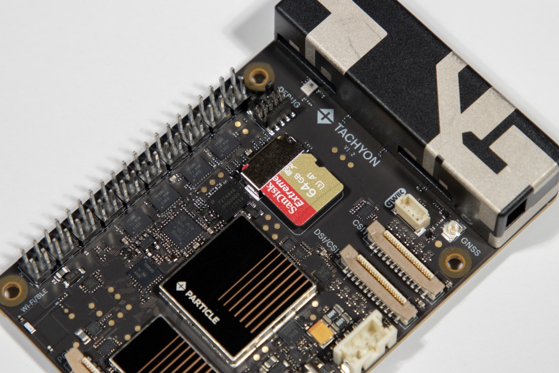
- Accepts standard SD cards
- Used for additional storage (OS is stored on internal flash)
For more information on installation and usage, see the dedicated SD Card section.
12. Raspberry Pi 40-Pin Expansion HAT Connector

- Follows the Raspberry Pi standard
- Enables HAT expansion for additional functionality
More Info: GPIO & IO Page
13. RTC Battery Connector
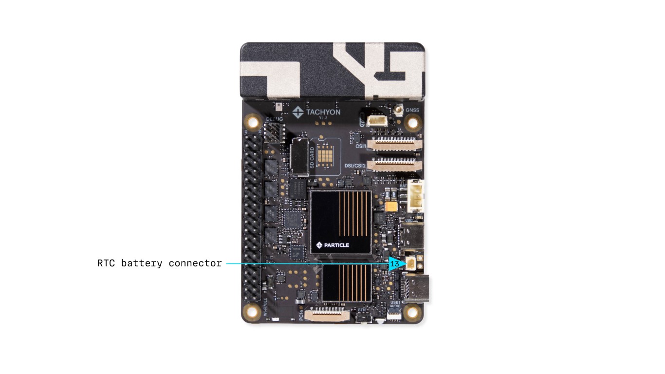
This connector is designed for an external RTC (Real-Time Clock) backup battery, allowing the system clock to maintain accurate timekeeping when the main power source is disconnected.
14. Wi-Fi/Bluetooth Antenna
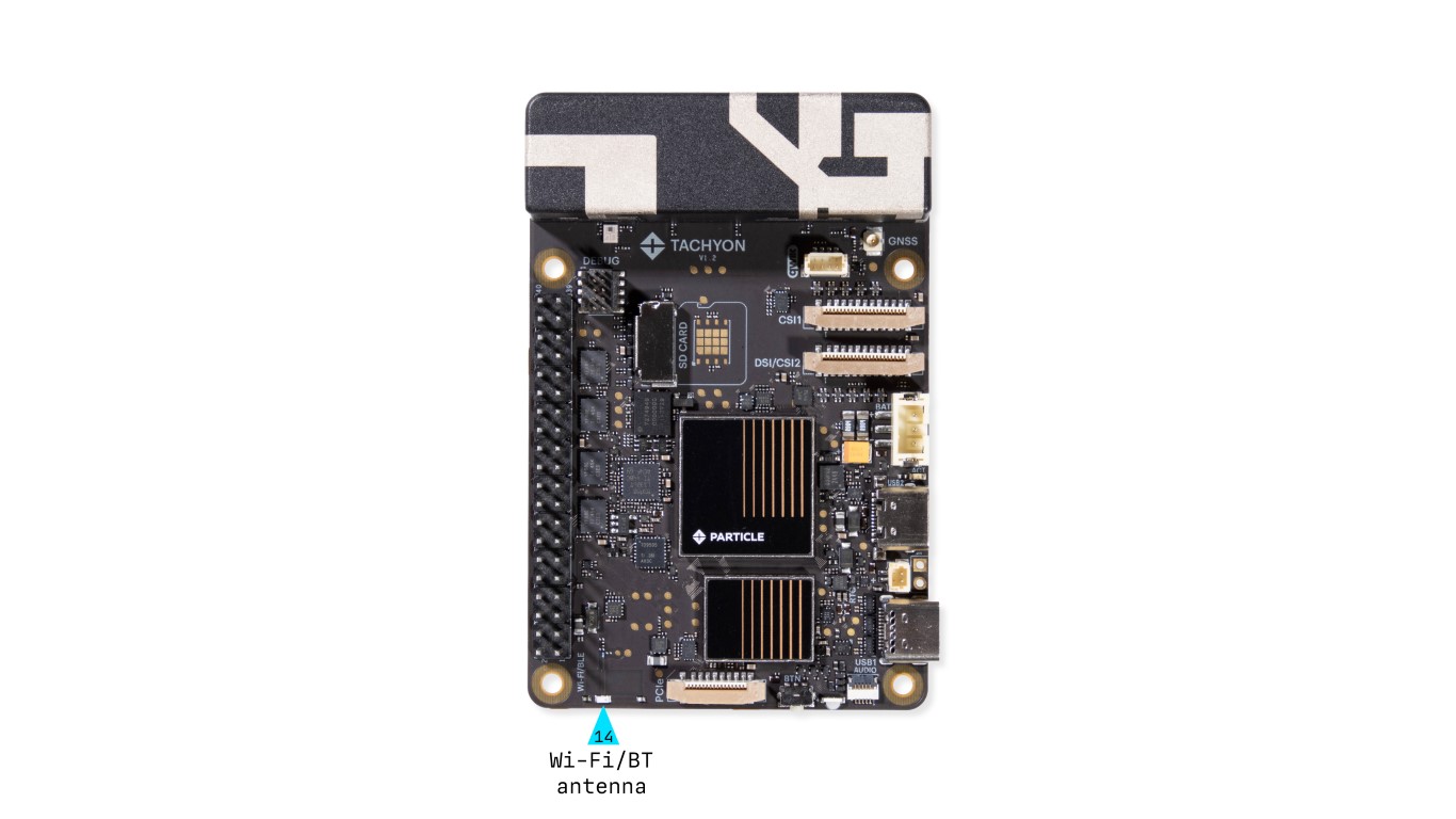
The onboard Wi-Fi/Bluetooth antenna supports both 2.4GHz and 5GHz bands, providing reliable dual-band wireless connectivity for a wide range of applications.
15. PCIe Expansion Connector
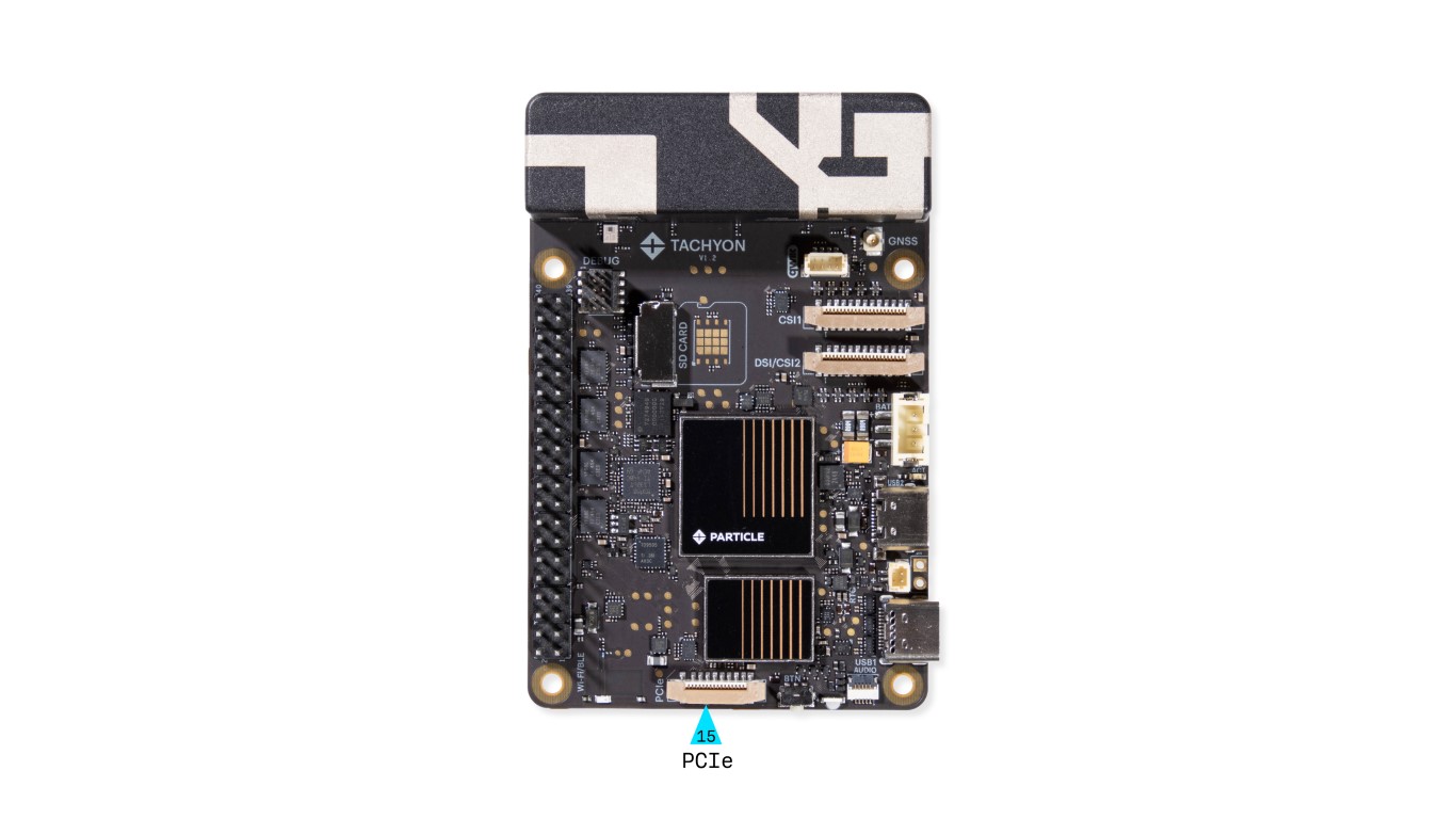
- Enables high-speed PCIe peripherals
- Used for NVMe SSDs, AI accelerators, and networking cards
For more information on using the PCIe interface, see the dedicated PCIe section.
16. Button
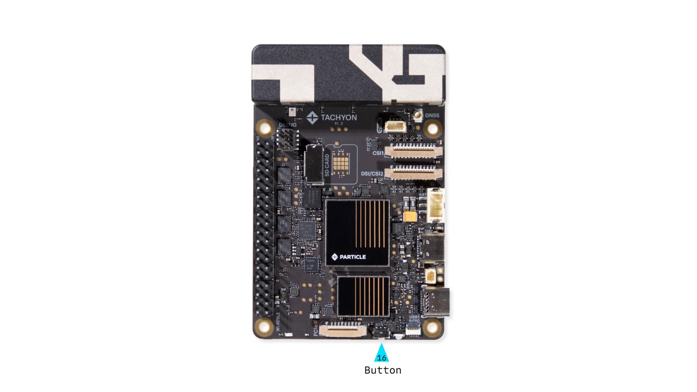
This is the primary multifunction button, with behavior that can be customized in software. It is located in the same position as on the Raspberry Pi 5.
Details on how to use and configure the button is available here.
17. Primary LED
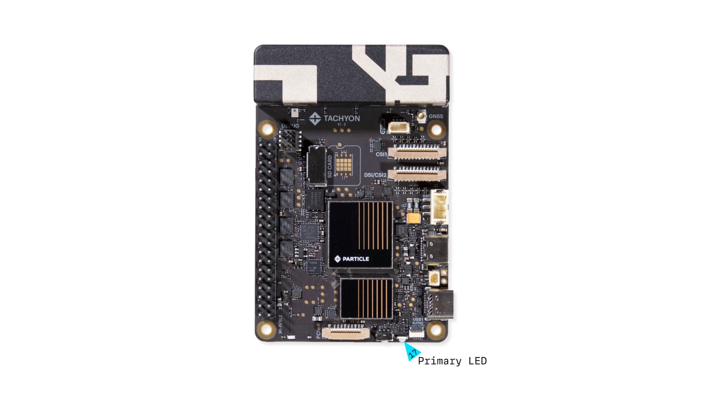
The Primary RGB LED displays top-level power status and system functionality. It indicates whether the board is connected, in power-off mode, updating, or experiencing an error.
We have a detailed section on LED behavior and usage here.
18. Audio Adapter Connector
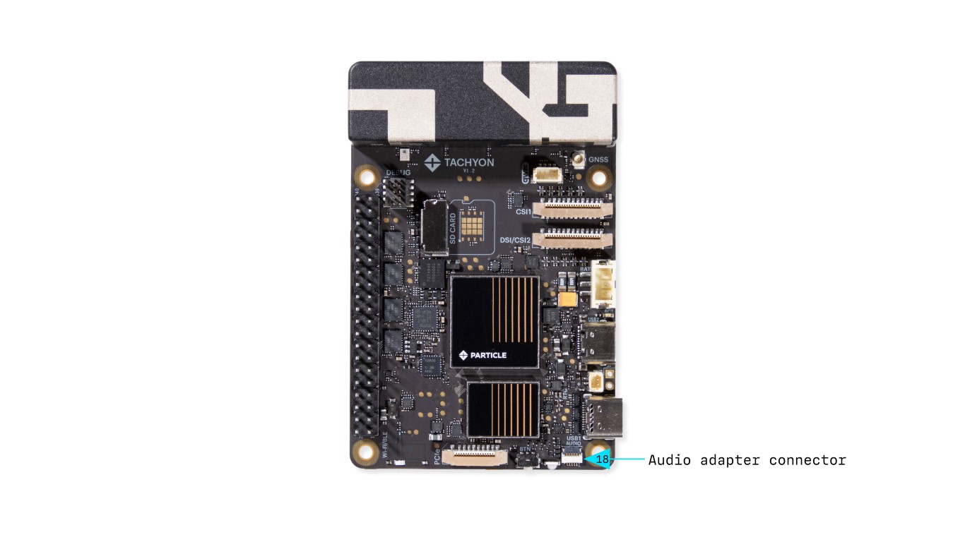
- 4-pin connector providing analog audio in/out
- Supports microphone input
Connects to the Audio Adapter.